hello,
Kelticwizard, i allready have one of those cobles you were on about and it was connected to my PC too.
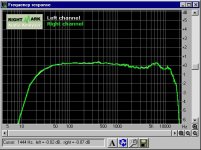
Anyway, i ran that RMAA program and the graph response should be below,
the response dosent really look too good, it seem as though it dosent make it to 15kHZ. I is however just the onboard sound card and not a PCI slot type.
Kram.
Kelticwizard, i allready have one of those cobles you were on about and it was connected to my PC too.
Anyway, i ran that RMAA program and the graph response should be below,
the response dosent really look too good, it seem as though it dosent make it to 15kHZ. I is however just the onboard sound card and not a PCI slot type.
Kram.
Attachments
Your sound card is better than my sound card, which isn't saying much, LOL.
Overall, I would say your sound card is pretty good. You are -1.5 dB-not -3 dB-from 19 Hz to 15,000 Hz. Pretty good, I would say.
I wonder why we were getting such outrageous readings when we tested your AR tweeters? Gad, could your microphone have been that bad? Or your AR tweeters?
One thing, you might want to check your "multimedia" in your Control Panel to make sure there is no boost or anything in the mic input. Mine has a selection in the mic section for bass boost-not in the Line In section.
Anyway, if you have a mic handy-any mike-check some selected tones from 13,000 Hz down to 1000 Hz through your tweeter. You can see that the tweeter should be flat down to 1300 Hz or so, then goes down. Let's see what the mic reading is.
You can either use the oscilloscope, or measure directly from the mic leads with your digital multimeter. When you measure, see if you can get a 2 digit reading on the multimeter. Your tweeter should be able to take up to a 4 volt tone from 13000 Hz to 1000 Hz. Let's see how flat the mic is.
I am going to work on Crossover Simulator to figure the values we need. The author, F4ier, a member here, said that it takes into account notch filters, etc.
I believe I could design a crossover for you "by the numbers", but phase has everything to do with acoustic output with crossovers, and this notch filter adds another wrinkle. That is why I think we should have some sort of method of measuring that is reasonably accurate. It doesn't have to be that accurate, just want to make sure that we are not wildly off.
kelticwizard said:
C) The TW010E1 might have been selected by you for it's cost. However, it's .4 inch, (10 mm) diaphragm would make it a good choice for anyone who wants good dispersion above 12,000 Hz, regardless of cost. What was the size of the driver that crossed into your tweeter? Generally, "beaming" is what causes harshness, and too large a driver for the frequency causes "beaming". I would think that for a 6,000 Hz crossover to be used, the midrange should be five inches or less-preferably less.
My driver is 5.25", beaming occured when I had had only the mid/woofer rolling off naturally both, low-end and high-end.
"beaming" causes harshness. Wow! I didn't know that, well, my driver is not succeptible to mid-beaming. Thanks for the tip!
Soundcards, oh man, c'mon you guys don't suffer poor performance and awful acoustic output! Even a Soundblaster Live! Value would be great. Response is ine to me except fro that little blip in freq.
Keltic, what and where is this "wrinkle" you speak of? Phase plot, where?
Well, Kram, it's been awhile since I checked back on this. I am contacting another member tonight. However, just one thing I want to report.
If you want a quick-and-dirty crossover just to get this project moving, use a 7.8 uF capacitor in series with the tweeter. This will give you a 6 dB crossover at 3400 Hz, which is where your woofer will rolloff naturally.
Fancier crossovers will take a little longer to put together, and as I mentioned before I am contacting someone else.
You mentioned in the previous thread that you might consider leaving the anomaly at 2000 Hz in if necessary. Well, this simple crossover will leave that in. I would prefer to give you a crossover that takes that roughness out. However, I just want to give you the option of having a crossover to put in in case you decide that you want to wrap the project up.
One more thing. The Audax website is down, so you cannot see all the stats for the TM025F1. However, Solen of Canada, a very respected retailer, lists the Re as 5.7 ohms and the Le as .04 mh. Anybody who wants to jump in and help on this crossover might wish to know that.
http://www.solen.ca/aud.htm
Incidentally, if you choose to use electrolytic capacitors, which are not the best for crossover work, use the nonpolarized kind. The others are useless. Also, do not use tantalum under any circumstances. Poly caps are fine-a little more expensive but not too much. They will make a difference on a fine tweeter like the Audax.
Hope to post more soon.
Bose:
Phase is very important in crossovers. It is too long a story to go into here, but let me say this. If two loads are entirely out-of-phase-that is, 180 degrees apart-they will cancel each other and you will have nothing. No output.
In fact, airlines have begun to use "anti-noise" in some planes where the immense noise from the jet engines is sensed by microphones, then electronically put 180 degree out-of-phase and then played through loudspeakers in the passenger area. Although there is a little delay because of the sound has to travel through the microphone and amp, the it is close enough to being completely out-of-phase, (180 degrees apart) from the source that the sound is deadened considerably.
As it is with sound, so it is with electronics. When you combine two signals that are completely in phase, you get double the amplitude of the signal. If they are out-of-phase, combining them will result in something less than double the amplitude and might even result in total cancellation, (no output at all).
It gets more complex than that. Capacitors make a signal go out-of-phase in one direction, and inductors the opposite way. If you have an amp with a capacitor in series with an inductor, at the frequency where the capacitor and inductor both have equal ohms, you get complete cancellation. The amp see zero ohms, and blows. The only ohms the amp will see is the DC resistance of the wire it took to wind the inductor-every inductor has some DC resistance. That is it. If the wire in the inductor had a resistance of 1/8 of an ohm, the amp sees 1/8 of an ohm-even though both the capacitor and the inductor are 30 ohms or more at that frequency!! Heck, they could both be 10,000 ohms at that frequency-it wouldn't make a difference.
I will search the web for a website with a quick-and-dirty explanation for this-it really is not that complex an idea in it's basic form, (though it leads to some mighty complex figuring when you have resistors, capacitors and inductors in series and parallel all in the same circuit).
Have not found the site yet. Looking for one. I could say, "Find a nice textbook on AC circuits" but I would bet the info is on the internet, and it only takes a few paragraphs to explain.
How does theta degrees fit in? Well,
A) if 0 degree or 360 degrees is exactly right-add two values that are either 0 degrees or 360 degrees apart and you get twice the amplitude
and
B) if 180 degrees is exactly wrong-add two values together 180 degrees apart and you get zero
then
if two values are added together that are not 0, 360 degrees or 180 degrees apart, then they must come out being something between twice the amplitude or zero amplitude. That value theta tells us what.
PS: It is not linear. It goes according to a sine wave.
Pinkmouse:
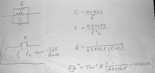
Thank you so much for the formula for the notch filter. Man, you are one precise guy-you take the value for 2 pi out to four decimal places!")
One thing, though. Looking over the equation, I see that the formula includes F or Frequency and C for Capacitor value. But the notch filter also includes an inductor, which is normally labelled L. Yet the formula for the notch filter contains no mention of L for inductance.
Since the inductor has just as much to do with the phase angle as the capacitor, are you sure there is no value for "L" in that equation? Or has the value of L already been converted into terms of F and C in the equation as written?
Just asking before I start figuring, (my math skills are limited enough as it is, LOL).
Thank you so much for the formula for the notch filter. Man, you are one precise guy-you take the value for 2 pi out to four decimal places!
One thing, though. Looking over the equation, I see that the formula includes F or Frequency and C for Capacitor value. But the notch filter also includes an inductor, which is normally labelled L. Yet the formula for the notch filter contains no mention of L for inductance.
Since the inductor has just as much to do with the phase angle as the capacitor, are you sure there is no value for "L" in that equation? Or has the value of L already been converted into terms of F and C in the equation as written?
Just asking before I start figuring, (my math skills are limited enough as it is, LOL).
Bose:
Haven't found the webpage for you yet but here is nice web page about crossovers that I think you might like. Explains a lot. It tells you at what level crossovers the drivers should be compared to the midpoint at various configurations: each driver should be 3 dB under the midpoint for first order crossovers, 6 dB under for second order, etc.
http://www.traymann.free-online.co.uk/xover_2.PDF
pinkmouse said:Talk about sad, when I was about 10 years old, I could recite pi to 100 decimal places
Don't tell me, let me guess. Your parents sent you away to one of those famous British boarding schools? Is that what they make those kids do there? (In America, the parents would sue the school for "Neuron Overload Abuse" or something).
Now, one more thing. I take the value of this equation for any frequency that is whithin the notch filter's range, correct?
I can get the phase angle of any woofer at any frequency just by plugging the Thiele small parameters into Subwoofer Simulator, a freeware program written by F4ier, a member of this forum.
Once I establish the phase angle for the frequency selected before the notch filter is added, do I just add that value to that value from this formula? So if the reactance is -20 degrees at the selected frequency before I add the notch filter, and the equation yields a value of +15 degrees with the notch filter, do I have a total phase angle with the notch filter of -5 degrees?
Anyhow, is the equation written correctly below?
p.s. Anyone know of an equation editor on the Mac OSX? (don't say M$ office!)
I would think that your fellow moderator, Planet 10, would be the man to ask for that one.
Attachments
kelticwizard said:Bose:
Haven't found the webpage for you yet but here is nice web page about crossovers that I think you might like. Explains a lot. It tells you at what level crossovers the drivers should be compared to the midpoint at various configurations: each driver should be 3 dB under the midpoint for first order crossovers, 6 dB under for second order, etc.
http://www.traymann.free-online.co.uk/xover_2.PDF
Thanks a lot Wiz, hopefully I can help you out on a project of your own some day.
Yup, Wiz, that's the one!
After thinking on this for a while, I'm not sure if we need to worry about phase angle too much, or even sorting out that peak. It might be worth while for a first cut just going for a 3k crossover with a standard second order Xover, or at least waiting on the in box measurements of the mid/bass driver, just to seee how bad it is in reality.
The reason I thought this was that I was going through a load of old back issues of Hi-Fi mags, and many commercial speakers have much worse dips and lumps than this, so although it may look nasty, it may not work out in reality to be so bad.
Hmmm, I don't know...
Regarding Pi, no i was just a sad kid!
After thinking on this for a while, I'm not sure if we need to worry about phase angle too much, or even sorting out that peak. It might be worth while for a first cut just going for a 3k crossover with a standard second order Xover, or at least waiting on the in box measurements of the mid/bass driver, just to seee how bad it is in reality.
The reason I thought this was that I was going through a load of old back issues of Hi-Fi mags, and many commercial speakers have much worse dips and lumps than this, so although it may look nasty, it may not work out in reality to be so bad.
Hmmm, I don't know...
AFAIK- the phase change is maximal at the centre frequency of the filter, and alters in proportion to the slope of the filter. As for the rest, yes!Now, one more thing. I take the value of this equation for any frequency that is whithin the notch filter's range, correct?
Regarding Pi, no i was just a sad kid!
Wow, I was surprised to see so many replies after my absence from the Internet over xmas, Thank you to you all.
kelticwizard
I will try that cap value that you suggested for the time being, then I will try whatever more complex xover you guys come up with later on. and we will see if i can hear the difference.
Thank you
Kram
kelticwizard
I will try that cap value that you suggested for the time being, then I will try whatever more complex xover you guys come up with later on. and we will see if i can hear the difference.
Thank you
Kram
- Status
- This old topic is closed. If you want to reopen this topic, contact a moderator using the "Report Post" button.
- Home
- Loudspeakers
- Multi-Way
- Xover design help