Has anyone tried this to get the most out of the low frequency of a driver in a box that's too small.
I tried it and it definatly makes the driver go an octave or two lower, but what I would like to know is what happens to the Qtc of the spearker in the box, does it go up or down or stay the same?
I've seen this done on Infinity Speakers, all the high end ones from years ago RS1, RS1b, RS4.5, RS Betas and such, when Infinty were highly regarded with their Emmits and Emmins mids and highs and had great bass from 12ins drivers that were capacitor coupled with huge caps as well.
Read at the bottom ( A Third Octave Sealed System)
http://www.subwoofers.cc/HomeAud/HDrivers/sv12alignments.htm
Cheers George
Greetings fellow "Digger". If I've understood it correctly then I think the first example I saw was a KEF 105 Series I (in mid 70's) where they used a 600uF cap in series with a sealed (second order) box. Auditioned very well from all reports. I gather it depends on starting with an underdamped response in the first place.
Can Ron or anyone give a fix to this, I'm almost there.
I'm not using the capacitor coupling, it was just an experiment.
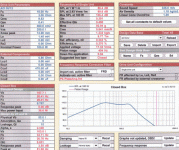
All working perfect SV12 in 85lt fully stuffed laid in but not squeezed in 75%wool 25%dacron batts, with my low pass now modded to only 5mh (instead of 10mh) and 470uf, Unibox gives me -3@35hz and Qtc of .708 and it sounds great.
But, there's always a but, the bass is just a little too loud around the peak of 60-80hz, is there any way of reducing it 2-3db without introducing a series resistance and blowing my Qtc to hell, or increasing the feedback on my bass amp? (pig of a job)
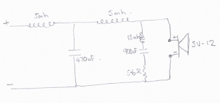
Below is the circuit of my xover I bridged out the 2ohm and bridged out the first 5mh choke, with 10mh I had not enough ooph around the 200hz with the 5mh it's just right but the total level is just a bit loud.
Thanks for the help George
Attachments
Is it at all possible to move the crossover down? My sealed Assassin sub sounded bloated in the 60-80 hz region also, so i moved the crossover down from 80 hz to 50 hz and it took away all the bloat but left me with the extension. What mains are you using? Are they capable of a lower crossover?
LightwaveDude said:Is it at all possible to move the crossover down? My sealed Assassin sub sounded bloated in the 60-80 hz region also, so i moved the crossover down from 80 hz to 50 hz and it took away all the bloat but left me with the extension. What mains are you using? Are they capable of a lower crossover?
They are Martin Logan Monolith III, electrostaic above the 125hz xover, they won't go down any further, guess it's the upping of the feedback on the bass amp to reduce bass a couple of db did'nt want to go that route, as both amps are pefect gain match at the moment.
I'll wait a few weeks, maybe the bass units and all the fresh stuffing will change for the better, (less) bass, or worse get more efficient and become even louder.
Cheers George
“the bass is just a little too loud around the peak of 60-80hz, is there any way of reducing it 2-3db without introducing a series resistance and blowing my Qtc to hell”
Have you tried this proposed method to control the Qtc (Qts):
http://www.diyaudio.com/forums/showthread.php?threadid=83982&perpage=10&pagenumber=3
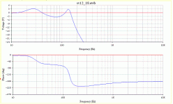
A picture showing voltage readings only considering the driver at the filter drive point, and if lowering Qms:
B
Thanks Bjorno, I will study this, as this is my first venture into speaker design, and i'm learning slowly, been building amps too long and never dabbled in the blak art of speaker design.
I have mange to flatten the response down a little by just the right amount and the 80hz mark, and it is sounding very good with studio recordings, nice and tight and dry, but with big orchestral pieces I actually prefer the way I thought it was too loud.
What I did was put an LCR network across the back of the SV12 which was 18mh-900uf-5.6ohm and that is perfect for studio done recordings closely miked double bass and such, but for big orchestral work that is distant miked I perfer it off.
Can you simulate what the LCR network is doing on your program? With the 5mh then 470uf to ground and the LCR across the SV12.
Cheers thanks for you intrest and help
Cheers George
George,
The Spice program I used in this case is Electronic Workbench 5.21, which has evolved into MultiSim and also the program to choose if you are interested in circuit simulations.
I think you will be very close to hit diminishing returns by changing the capacitor from 900 uF to 1100 uF.
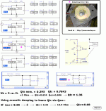
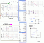
See the submitted pictures.
What you are really doing is making the filter load acting more linear (approaching text book filters) when tuning the LCR but not trimming the Qtc value which should give more in return if chosen together with your actual room gain, the default FR to match.
Why not measure your speakers Qtc with this simple method:
Measure SPL (mass) without filter where the speaker is mass controlled and shows a constant SPL a bit above fc and SPL (fc) at fc, in your case about 35 Hz. Then Qtc is: 10^((SPL(fc)-SPL(mass))/20 .
Now try the method a described earlier addressing driver Qms.
If your bass speaker were positioned close to a wall (0,5 m), I would roughly target a Qtc between 0,5-0,6 and if also close to a corner 0,4-0,5 but you may have other preferences for Qtc limits to use and that’s fine too.
B
Attachments
Looks as though it's about as fine tuned as I'm going to get with my limited knowledge, thanks for all your help Bjorno, but the last two measurements you said i should make kinda lost me.
I think that the only way to imporve the bass from here is if were actively cross over with 24db slope at around 250-300hz, as I'm a minimalist person who hates to have too much electronics (too many IC's) between the source and the poweramps I'm loathed to go that way, I have a thing about it, read here:
http://www.diyaudio.com/forums/showthread.php?s=&threadid=80194
If i could I'd have the cd player driving the speakers.
Thanks again George
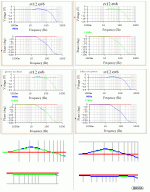
Tried this last night Bjorno, 18db per octave seems to be the best I've had so far, if you don't mind plotting it.
The Electrostatic panel seems to start rolling off at 200hz at whatever the crossover the rate is, looks to me to be 12db per octave? Should the esl be in the same phase as the bass now that the bass is 3rd order or should it be out of phase.
The Electrostatic panel seems to start rolling off at 200hz at whatever the crossover the rate is, looks to me to be 12db per octave? Should the esl be in the same phase as the bass now that the bass is 3rd order or should it be out of phase.
Attachments
George,
Let me first tell you why your filter tweaking in the mid bass, only is possible to a certain extent without actually doing acoustical measurements.
Your suggested LCR circuit did luckily not alter the crossover or affected the low end so far but your latest suggestion with 18 dB filters turns in my opinion everything into the realm of “Black Art design”.
Implications for the drive voltage: See the submitted plot.
I must also here stress, I think speaker building is mostly (maybe 90%) “Engineering” and the use of microphone measurements of FR and phase are foundations in this matter, if ever a good sounding multi driver speaker system is the goal and be meet with reasonably efforts, this without unnecessary time consuming guess work.
I also vote for the knowledge of psychoacoustics Example: http://interface.cipic.ucdavis.edu/CIL_tutorial/3D_psych/3D_psych.htm, and not to forget psycho music’s findings that describe listening on the highest level using music notations and compared with psycho acoustic observations.
A very good source can be found here: http://psy.ucsd.edu/~ddeutsch/psychology/deutsch_publications.htm
Among more from Diana Deutsch, why not read this paper: http://philomel.com/pdf/PsychMus_Ch9.pdf
The rest to consider and always there when building speakers in general, maybe in the % range, is from the fact that Music is an Art and therefore the only art form to take into consideration when constructing speakers together with your own preferences colouring the end result.
I will only comment the first sentence because I don’t care how many parts are involved in audio as long as they are acting blameless in a chain, doing exactly what they are supposed to do.
Of course, except for those parts that are redundant and only occupies unnecessary space and cost extra money.
Back to business:
250-300 Hz and an electrical 24 dB slope filter will increase the actual acoustical low pass slope probably to more than 36 dB/ octave due to the FR limit and acoustic phase of the driver, not to forget the high Le together with Re which introduces an extra pole.
I think this sub optimises your speaker.
Read this good paper that applies both to speakers and amplifiers:
http://users.ece.gatech.edu/~mleach/papers/phasedist.pdf
Question:
What is the recommended upper usable corner frequency for your driver?
Is it about 300 Hz and really an original ACI driver or is it as for the later Meniscus only 100 Hz?
Meniscus SW1284 a/k/a the ACI SV12 : http://ldsg.snippets.org/vendors/meniscus.php3
; SW1284 at http://www.meniscusaudio.com/speakercomponents/
Though I don’t exactly know the upper end of the FR and phase curve for your woofer I will briefly sum up what I can read out from your submitted Unibox data:
As can be seen from your Unibox data sheet:
Your SV12 driver is a type of high Qts/Vas/Le and together with high Qm and will optimally suit a box with a volume of 167 L at the compliance ratio alpha = 250/167 = 1.497.
In this case, this would make your box to be of an IB type that really suits the driver.
This IB speaker box does not alter negatively the FR response or the minimum phase behaviour in the mass controlled section of the driver FR, starting over about 35 Hz and is least sensitive near 80 Hz and relies mostly of actual T/S data.
The volume also optimises the – 3dB point and the cut-off frequency, fc to be as low as possible together with a flat FR-curve without the problems you are trying to circumvent in the mid bass.
Lowering the optimal volume from 167 L to 85 L pushes the compliance ratio up causing Qtc to move upwards to about 0.83.
This makes the speaker to peak in the mid bass at about 51 Hz with a magnitude of about 3-4 dB and the whole will only sound right if only you are lucky tweaking the bump without affecting the rest of the FR or the acoustic phase response at the lowest end or at the crossover point.
Less volume than optimal also forces the speaker into near an AS type of speaker (acoustic suspension) where the chosen volume dominates the high-pass performance at the lower FR end.
The speaker becomes sensitive for stuffing of absorbent materials.
The IB box is easy to stuff with sound absorbing materials to suit a chosen driver-box Qmc that always must be done in advance to hit a target Qtc, but is more sensitive in your case when a 50 % lower volume is chosen.
I recommend you to first read: http://users.ece.gatech.edu/~mleach/;
Download: QTCvsQMC.pdf
Then from the same source: Download: closedbox.pdf
You have not supplied data for the box stuffing but if the Unibox-data is reliable Qb (total losses) can be calculated to 1/Qb = 1/Qa + 1/Ql; Qb = 1/5 + 1/15 = 3.75 that indicates high losses and thus the absorption losses loads Q of the speaker, often a unknown extent and if this is the case in the reality, it has to be measured after the speaker is build.
The nominal volume will also act like ‘magnified’ from 85 L to about 103 L as can be seen in the Unibox-data.
Is it still possible to correct your reported mid bass problems without doing acoustical measurements?
Yes, but as soon as you connect an electrical filter the minimum phase behaviour of the speaker is lost, the filter phase response adds to the driver phase but for your case the crossover point is enough far away to be affected if you keep the original crossover point determined of an unchanged high pass section and slope definition.
This also implies that the low pass cannot be of higher order than about two if you still want a straight acoustic FR curve without a big dip.
I guess the Monolith III filter you first supplied is correct for the IB case (‘monolith 3 passive crossover schematic’) but not for your sized down version and that caused your problems in the first case.
More:
When I first looked at your Monolith 3 passive crossover I tried to estimate the transformer load for the high-pass section.
I run a couple of Spice simulations and found that the transformer in best case should have an equivalent impedance around 3.5 Ohm for absence of filter ringing effects and very close to a resulting 12 dB/octave slope with a – 3dB point at about 185 Hz.
Impedances over 4 Ohm lower the – 3 dB point but make the filter to ring severely.
Then I turned to examine the low-pass section and noticed the 2-Ohm resistor in series with the inductors and it’s losses I estimated to sum in the very best case, to be about 2 times 0.5 Ohms, thus a resistive sum to equal 3 Ohms.
3 = 2 x PI x f x L (L = 10 mH) gives f about 48 Hz where the inductor slope levels out and leaving only Le to further attenuate at about f = Rdc/(2 x PI x Le), f = 329 Hz.
I think this phase shift at 48 Hz together with the peak at 51 Hz is a disaster for your FR performance.
Changing the capacitor in your LCR from 900 uF to a higher value causes the low pass crossover to overlap the high pass too much but flattens out the low end positively.
You can try C values up to 1500 uF that improves the FR at low bas but makes your speaker FR of no use over 100Hz.
Obviously you made the right decision when omitting one of the inductors (and included the LCR), but without acoustic measurements it’s impossible to know if the right value are 3,3 - 5 mH and the driver shunt capacitor somewhere between 390-470 uF.
FR loobing issues’ coming from physical implementation and the lack of acoustic measurements from your speakers makes it impossible to predict what’s best practice to recommend.
B
Edit: A lot of commas and space added!
Let me first tell you why your filter tweaking in the mid bass, only is possible to a certain extent without actually doing acoustical measurements.
Your suggested LCR circuit did luckily not alter the crossover or affected the low end so far but your latest suggestion with 18 dB filters turns in my opinion everything into the realm of “Black Art design”.
Implications for the drive voltage: See the submitted plot.
I must also here stress, I think speaker building is mostly (maybe 90%) “Engineering” and the use of microphone measurements of FR and phase are foundations in this matter, if ever a good sounding multi driver speaker system is the goal and be meet with reasonably efforts, this without unnecessary time consuming guess work.
I also vote for the knowledge of psychoacoustics Example: http://interface.cipic.ucdavis.edu/CIL_tutorial/3D_psych/3D_psych.htm, and not to forget psycho music’s findings that describe listening on the highest level using music notations and compared with psycho acoustic observations.
A very good source can be found here: http://psy.ucsd.edu/~ddeutsch/psychology/deutsch_publications.htm
Among more from Diana Deutsch, why not read this paper: http://philomel.com/pdf/PsychMus_Ch9.pdf
The rest to consider and always there when building speakers in general, maybe in the % range, is from the fact that Music is an Art and therefore the only art form to take into consideration when constructing speakers together with your own preferences colouring the end result.
“I think that the only way to imporve the bass from here is if were actively cross over with 24db slope at around 250-300hz, as I'm a minimalist person who hates to have too much electronics (too many IC's) between the source and the poweramps I'm loathed to go that way, I have a thing about it, read here:
I will only comment the first sentence because I don’t care how many parts are involved in audio as long as they are acting blameless in a chain, doing exactly what they are supposed to do.
Of course, except for those parts that are redundant and only occupies unnecessary space and cost extra money.
Back to business:
250-300 Hz and an electrical 24 dB slope filter will increase the actual acoustical low pass slope probably to more than 36 dB/ octave due to the FR limit and acoustic phase of the driver, not to forget the high Le together with Re which introduces an extra pole.
I think this sub optimises your speaker.
Read this good paper that applies both to speakers and amplifiers:
http://users.ece.gatech.edu/~mleach/papers/phasedist.pdf
Question:
What is the recommended upper usable corner frequency for your driver?
Is it about 300 Hz and really an original ACI driver or is it as for the later Meniscus only 100 Hz?
Meniscus SW1284 a/k/a the ACI SV12 : http://ldsg.snippets.org/vendors/meniscus.php3
; SW1284 at http://www.meniscusaudio.com/speakercomponents/
Though I don’t exactly know the upper end of the FR and phase curve for your woofer I will briefly sum up what I can read out from your submitted Unibox data:
As can be seen from your Unibox data sheet:
Your SV12 driver is a type of high Qts/Vas/Le and together with high Qm and will optimally suit a box with a volume of 167 L at the compliance ratio alpha = 250/167 = 1.497.
In this case, this would make your box to be of an IB type that really suits the driver.
This IB speaker box does not alter negatively the FR response or the minimum phase behaviour in the mass controlled section of the driver FR, starting over about 35 Hz and is least sensitive near 80 Hz and relies mostly of actual T/S data.
The volume also optimises the – 3dB point and the cut-off frequency, fc to be as low as possible together with a flat FR-curve without the problems you are trying to circumvent in the mid bass.
Lowering the optimal volume from 167 L to 85 L pushes the compliance ratio up causing Qtc to move upwards to about 0.83.
This makes the speaker to peak in the mid bass at about 51 Hz with a magnitude of about 3-4 dB and the whole will only sound right if only you are lucky tweaking the bump without affecting the rest of the FR or the acoustic phase response at the lowest end or at the crossover point.
Less volume than optimal also forces the speaker into near an AS type of speaker (acoustic suspension) where the chosen volume dominates the high-pass performance at the lower FR end.
The speaker becomes sensitive for stuffing of absorbent materials.
The IB box is easy to stuff with sound absorbing materials to suit a chosen driver-box Qmc that always must be done in advance to hit a target Qtc, but is more sensitive in your case when a 50 % lower volume is chosen.
I recommend you to first read: http://users.ece.gatech.edu/~mleach/;
Download: QTCvsQMC.pdf
Then from the same source: Download: closedbox.pdf
You have not supplied data for the box stuffing but if the Unibox-data is reliable Qb (total losses) can be calculated to 1/Qb = 1/Qa + 1/Ql; Qb = 1/5 + 1/15 = 3.75 that indicates high losses and thus the absorption losses loads Q of the speaker, often a unknown extent and if this is the case in the reality, it has to be measured after the speaker is build.
The nominal volume will also act like ‘magnified’ from 85 L to about 103 L as can be seen in the Unibox-data.
Is it still possible to correct your reported mid bass problems without doing acoustical measurements?
Yes, but as soon as you connect an electrical filter the minimum phase behaviour of the speaker is lost, the filter phase response adds to the driver phase but for your case the crossover point is enough far away to be affected if you keep the original crossover point determined of an unchanged high pass section and slope definition.
This also implies that the low pass cannot be of higher order than about two if you still want a straight acoustic FR curve without a big dip.
I guess the Monolith III filter you first supplied is correct for the IB case (‘monolith 3 passive crossover schematic’) but not for your sized down version and that caused your problems in the first case.
More:
When I first looked at your Monolith 3 passive crossover I tried to estimate the transformer load for the high-pass section.
I run a couple of Spice simulations and found that the transformer in best case should have an equivalent impedance around 3.5 Ohm for absence of filter ringing effects and very close to a resulting 12 dB/octave slope with a – 3dB point at about 185 Hz.
Impedances over 4 Ohm lower the – 3 dB point but make the filter to ring severely.
Then I turned to examine the low-pass section and noticed the 2-Ohm resistor in series with the inductors and it’s losses I estimated to sum in the very best case, to be about 2 times 0.5 Ohms, thus a resistive sum to equal 3 Ohms.
3 = 2 x PI x f x L (L = 10 mH) gives f about 48 Hz where the inductor slope levels out and leaving only Le to further attenuate at about f = Rdc/(2 x PI x Le), f = 329 Hz.
I think this phase shift at 48 Hz together with the peak at 51 Hz is a disaster for your FR performance.
Changing the capacitor in your LCR from 900 uF to a higher value causes the low pass crossover to overlap the high pass too much but flattens out the low end positively.
You can try C values up to 1500 uF that improves the FR at low bas but makes your speaker FR of no use over 100Hz.
Obviously you made the right decision when omitting one of the inductors (and included the LCR), but without acoustic measurements it’s impossible to know if the right value are 3,3 - 5 mH and the driver shunt capacitor somewhere between 390-470 uF.
“Should the esl be in the same phase as the bass now that the bass is 3rd order or should it be out of phase.”
FR loobing issues’ coming from physical implementation and the lack of acoustic measurements from your speakers makes it impossible to predict what’s best practice to recommend.
B
Edit: A lot of commas and space added!
Attachments
WOW, so much to learn, so little time. Thanks for all your help Bjorno. for the meantime it sounds the best to my ear with the 3rd order xover without the lcr network, it gives me the best upperbass 150-300 i've had without seaming to muddle too much with the low end of the esl panels, and still goes low and tight, even though the QTC maybe up around .85 because of all the resistance in the air core chokes, it still sounds tight and has good upper extention.
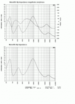
Just for intrest i have the ML measured impedence graph attached. Till I get a play with an electronic xover i think it's the best i can do without more knowledge.
Cheers george
Just for intrest i have the ML measured impedence graph attached. Till I get a play with an electronic xover i think it's the best i can do without more knowledge.
Cheers george
Attachments
- Status
- This old topic is closed. If you want to reopen this topic, contact a moderator using the "Report Post" button.
- Home
- Loudspeakers
- Multi-Way
- Has anyone tried this!
