Like, I am sure, a lot of you, winding one's own inductor has a lot of appeal. With the cost of an audio grade inductor being quite high (more than the speaker in many cases), and with an inductor being nothing more (in concept, at least) than some wire rolled on a spool, it would seem to be an easy thing for the DIY'er to do.
However, it seems few of us are winding our own inductors. I think there are two primary reasons for this: many of us don't have accurate inductance meters and, well, it is plain painful to wind inductors. Let's look at these issues in detail.
1. The cost you could save from winding your own inductors may very well more than pay for a decent inductance meter (or, alternately, a test setup from which to accurately measure inductance). Even if you have a meter or bridge, however, it is still difficult to determine the exact inductance as you are wiring. To measure as you go, you would have to pierce the wire's insulation - not a good thing. If you cut the wire too soon and too short, you are hosed -- splices in an inductor can't be good! I would hate to wind a 1 mH inductor with 10 AWG wire and find I ended up at .9 mH! On the other hand, I would hate to further tear up my hands and wind on a couple of extra layers of wire and find out I have a 2 mH inductor.
2. While winding a piece of wire on a form is simple in theory, it is very hard on the hands. Large diameter wire does not like to be tighly wrapped around a small core, and it is difficult to keep the windings evenly spaced and layered. While it can be done by hand, it is slow and painful. Some use a slow-turning lathe or a hand crank to help, but you still need to use your hands to keep tension and to route the wire. No wonder people buy inductors!
But, there may be another, much easier way. As any of us who have done some electrical wiring about the house knows, most every hardware store sells electrical wiring in boxes of 25 feet, maybe less. This wiring is spooled up and is one nice, big inductor! I don't have an L meter handy and have never tried to measure the inductrance of a box of house wiring, but I am sure a 25 foot lengh of wiring produces a lot more inductance than most any crossover network needs - and it only costs a few dollars.
A roll of 14-2 house wire has three 14 AWG wires. If we connect the ends together in parallel, this is equal to about a 9 AWG wire, I believe. So, why not take a spool of this this common house wiring, measure the inductance, then start clipping it back to get to the desired inductance?
The size of the spool is on the order of maybe 4" inside diamter to 8" outside diameter, but I don't think that using large diameter air core inductors is bad compared to smaller diameter, tightly wound inductors and, in fact, might be better as there would be fewer layers.
If anyone tries this, you might want to rough cut the wire to about 10% over value, then use wire ties or tape to start tightening up the coil, as it will be pretty loosely bound in the box (meaning the inductance could shift). As you continue to trim, you would continue to tighten up the coil so that when you are done trimming, you have a tight coil or wire that you can firmly secure to prevent the coil from later expanding.
Any reasons why this would not work?
The wire in a box is a good idea, but 25' is not very much. Using this
http://www.oz.net/~coilgun/mark2/inductorsim.htm
I couldn't get more than 0.2mH out of any configuration of 9 meters of 14 gauge wire. Now, I didn't try very hard, but I doubt this will be a suitable technique for larger valued inductors. I like the idea of using prewound magnet wire bobbins better.
better to waste 3m than 15m
I had the same dilemma when winding some coils the other night..... when to stop..... it is difficult to keep accurate count, so when I reach approx the right no of layers, I wind on an extra layer and a half or so...., then gingerly cut the wire (with teeth gripped)....
doing this my first initial inductance was 0.47 (wanted 0.33), the next night I was more daring and got to 0.37 initially..... better to waste a few metres than 15metres, plus the bits left over will be useful for something else - like nice thick hardwiring pieces etc etc, surely if you really need to the leftovers could be joined with solder/heatshrink and wound up anyway......
it certainly does work out cheap thats for sure, I made 4 0.33mH coils from 2mm wire for A$26..... web prices for same using 1.2mm wire were A$20 each..... nice saving for me.... work well too.
Well, it looks like my house wiring idea won't fly. I forgot that as wire guage goes down and coil diameter goes up, the inductance goes down rapidly.
Nelson's idea, vouched for by kiwi, does seem like a great idea. Thanks. Mag wire is relatively cheap, I think.
I simply hate the idea of spending $$ on a high end audio crossover inductor that is little more than a spool of magnet wire.
Jeff R
Nelson's idea, vouched for by kiwi, does seem like a great idea. Thanks. Mag wire is relatively cheap, I think.
I simply hate the idea of spending $$ on a high end audio crossover inductor that is little more than a spool of magnet wire.
Jeff R
I think we are oversimplifying the problem a little too much,
inductors are usually wound and then dipped in varnish or fastened together in some fashion, inductor will mechanically resonate just like caps if you ever used a large size cap to AC couple an amp you'll know what I am talking about.
You can build a variac with a plastic bucket full with salty water and a couple of cu plates, but do you really want to do that??
If you are just putzing around and experimenting that's fine, if you on the other hand want to build a semi-permanent setup you don't have to spend a fortune on audio grade inductors but you should try and do things a little more appropriately. By the way, I am pretty sure inductors can be calculated before hand.
Look up the formulas in some EE book.
look these up
http://www.oz.net/~coilgun/mark2/inductorsim.htm
http://www.colomar.com/Shavano/inductor_info.html
quite accurate from what I have rolled up.... I use some 50mm PVC pipe as a core, with two scraps of mdf with 50mm holes in as sides, makes a form adjustable for height, just slide the sides along (I fix them with screws) and wind away......
I'm not sure the varnish would make a great difference, as long as the coil is tightly held in place by something, I use cable ties, about 10 per coil. Would make tweaking at a later stage less of a nightmare......
I picked up magnet wire in Brisbane (Australia) for A$13.20 a kg last week (2mm wire)
look these up
http://www.oz.net/~coilgun/mark2/inductorsim.htm
http://www.colomar.com/Shavano/inductor_info.html
quite accurate from what I have rolled up.... I use some 50mm PVC pipe as a core, with two scraps of mdf with 50mm holes in as sides, makes a form adjustable for height, just slide the sides along (I fix them with screws) and wind away......
I picked up magnet wire in Brisbane (Australia) for A$13.20 a kg last week (2mm wire)
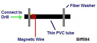
I don't know if this would work -- but I've wound solenoids out of magnetic wire before-- I put a thin piece of PVC pipe in a drill set to low speed and hot-glued the magnetic wire to one end with two fiber washers on either side of the pipe. Then I just guided the magnetic wire up and down- it worked pretty well and I got a nice, uniformly wound coil.
-Brian
-Brian
Attachments
Hi All,
Things seem complicated sometimes!
This is how I do.
Method-1 (With test equipment)
1) Take a transformer bobbin. (Plastic or other insulating material)
2) Do an Induction calculation for a squire or round winding.
3) Wind 75% of the coil.
4) Stop winding and scratch a small position of the coil, without cutting.
5) Beg/Borrow/Steal or Buy an LCR meter
6) Measure the coil from the starting of the coil and to the scratched part of the coil with an LCR meter.
7) If it is less wind more.
8) If it is high unwind
9) Measure again (You will be knowing approx. how much to do what).
10) Finally cut the coil and remove the bobbin.
11) Measure again to conform, for induction and resistance.
12) Varnish it and dry it properly in the sun or Hair dry it.
13) Mount it in the enclosure with RTV or with the with brass screw. No iron.
Method-2 (Without your own test equipment)
1) Take a transformer bobbin. (Plastic or insulating material)
2) Do an Induction calculation for a squire or round winding.
3) Wind more that required in the calculation.
4) Take the coil elsewhere who has an LCR meter
5) Measure the coil for induction and resistance.
6) Unwind the coil, don’t cut but scratch
7) Measure the coil from the starting of the coil and to the scratched part of the coil.
8) Cut and finish the job.
9) Measure again to conform, for induction and resistance.
Method-3 (Without test Equipment)
1) Take a transformer bobbin. (Plastic or insulating material)
2) Do an Induction calculation for a squire or round winding.
3) Assume your winding/calculation is ok and do the rest.
4) Measure to conform, for resistance if you have a multi-meter.
I hope this is of use to somebody, if you need big inductors buy various copper coils, which comes for winding transformers and use it. (I don’t know how many sizes it comes in, but it comes in all gauges of diameter.)
Mallick
Poor man's inductance measurement
Get a good quality cap e.g. MKP mettalised polypropylene of 5% tolerance or better. Put it across your inductor. Put a 100 ohm resistor in series with the parallel LC combination. Run the free end of the resistor to the + output terminal of a solid state amp. Run the non-resistor end of the LC to the - output of the amp. Put an AC meter or scope across the LC. Sweep a low to high frequency sinewave and watch the meter / scope for a tuning peak. You know the cap value and the resonant frequency, now go calculate the inductance.
Get a good quality cap e.g. MKP mettalised polypropylene of 5% tolerance or better. Put it across your inductor. Put a 100 ohm resistor in series with the parallel LC combination. Run the free end of the resistor to the + output terminal of a solid state amp. Run the non-resistor end of the LC to the - output of the amp. Put an AC meter or scope across the LC. Sweep a low to high frequency sinewave and watch the meter / scope for a tuning peak. You know the cap value and the resonant frequency, now go calculate the inductance.
Re: Poor man's inductance measurement
That's a simple trick, you could go one step further if you prefer.
You could alternatively get a 1% cap. or buy the 5% caps. and measure this in a Lab or friends place and write the values on it, then stick a transparent tape on the values, so they do not erase while handling the component. This will be your reference cap.
After measuring your coil you could recheck and label the same with the values. This could be your reference Inductors, and will help you to find the value for the caps. for your crossovers.
Good luck and Merry Christmas to all
Mallick
Many good ideas on this thread. I also roll my own inductors and most of my trannies. At the beggining did not have a bridge and so I calculated, not enough precison.
Later bought an LCR bridge And think this is a must for every DIY. Do your self a favor, stop buying so many multimeters and save for one. You can find used ones at atractive prices, try eBay or your local surplus equipment dealer. when i bought mine it changed my capacity as DIY audio. The bridge is as important as a multimeter and scope IMO.
The scratch method to measure inductance is very handy I also use it myself. I dip coils on varnish that will be used with high voltage and current, but do not varnish coils to be used as XO, never the less it's a good idea to do so.
As many, I also use magnet wire but think the electrical cable is not that good idea because you will end with more bulk and DCR because you will need more lengh of the same Ga wire to build a certain value plus magnet wire is way less expensive.
The tighter the winding the more inductance you will have, aspect ratio will also afect your inductance and final DCR (lenght of wire).
For up to 18 or maybe 16 Ga. I only use tape around the toroid and in some cases over the tape I'l thead a small dia cotton thread (old style) the way they use to bundle electrical cables on equipment.
For bigger coils or coils to be varnished It's very usefull to bind with nylon straps as someone suggested previously (don't use polyprop.or ployethylene) and then use a layer of cotton tape (you can varnish this one too) or a good quality electrical tape.
To varnish I keep a one galon can and just dip it inside for 10 or 15 minutes, the let it drip for some time and let it dry at the sun.
Do varnish in open areas, solvents are present.
Some times before varnishing, specially on cold or humid days, its good to warm the coil over an electric stove (at a distance above) to about 70°C or even more (depending of the type of straps you are using) this will dry most of the condensed water at the coil. Then dip it over the varnish ( free air electric type). To dry on those days you can also use the stove methode, only that now it will drip so add a metal pan over the stove ( not so hot to avoid burning the drops). Of course the pan will be used only for these purposes after your initial work.
Re: Need help designing the top
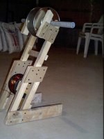
Chris, I hope your not thinking of winding the coil over the pipe.
Assuming you will be making an air core inductor:
What I would do with the setup you show is to build a smoth cylindrical but somewhat conical core were you will build the winding. Most likely a machine turned piece made of hard wood or metal with a cental hole to pass the shaft, you don't need a 1" dia. shaft for that, maybe a 1/2" solid will do.
The other thing to solve is how you will attach the side plates for containing the winding. A simple solution would be to put a couple of srews to hold them to the core mandrel. The other way would be (somewhat more costly or complicated to build) to have the shaft with thread on the area of the mandrel and add two nuts to press the plates against the mandrel.
Care should be given to size the coil in relation to the wire cross section this will help to keep the coil from deforming when you take out the plates and core. You can help to retain the build by adding adesive tape every two or five layers around the coil.
One last thing you may want to consider is adding a crank to the shaft.
chris ma said:I need some ideas to build the top wheel and able to remove the coil after winding,
Any ideas?
Chris, I hope your not thinking of winding the coil over the pipe.
Assuming you will be making an air core inductor:
What I would do with the setup you show is to build a smoth cylindrical but somewhat conical core were you will build the winding. Most likely a machine turned piece made of hard wood or metal with a cental hole to pass the shaft, you don't need a 1" dia. shaft for that, maybe a 1/2" solid will do.
The other thing to solve is how you will attach the side plates for containing the winding. A simple solution would be to put a couple of srews to hold them to the core mandrel. The other way would be (somewhat more costly or complicated to build) to have the shaft with thread on the area of the mandrel and add two nuts to press the plates against the mandrel.
Care should be given to size the coil in relation to the wire cross section this will help to keep the coil from deforming when you take out the plates and core. You can help to retain the build by adding adesive tape every two or five layers around the coil.
One last thing you may want to consider is adding a crank to the shaft.
End plates for coils.
Maybe we can use rejected/damaged Cd's or CD-R's as end plates for the coils. Can cut it down to size as required.
Insert a pvc tube that fits the hole size ( or increase the hole size) and glue it with epoxy or equivalent. The quick set type would be useful. Leave the extended tube in place till the winding is over and then cut off the excess. A hole at the end of the tube with a rod inserted would act as a crank to rotate the tube for winding the coil.
An even sturdier former could be made if you insert another tube over the tube used in the explanation above. This bigger tube would be the length ( or height) of the coil and would keep the CD's spaced apart as required. The glue on this would hold the end plates very well I guess.
- Status
- This old topic is closed. If you want to reopen this topic, contact a moderator using the "Report Post" button.
- Home
- Loudspeakers
- Multi-Way
- Different way to wind inductors?