Awhile back I posted several questions here
It was about a senior High School engineering project. We were allowed to pick any design problem we wanted, and I chose to do something in audio.
The presentation is done and over with (95/100), and now i'm ready to hear what real critics have to say with the design. Before you make a comment, please realize that
THESE ARE NOT IDEAL CONDITIONS!
i e=
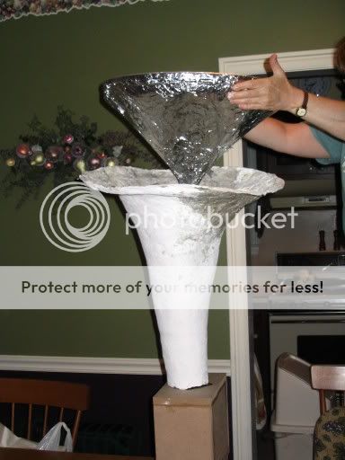
Paper Mache is not a good horn material (but it worked shockingly well)
Aluminum Foil is not the best reflective surface (maybe if it was thoroughly glued down)
a BS3 is not a very good horn loudspeaker.
and there are more.
It simply had to be a proof of concept.
What I am interested in is your expert opinions on the origional concept.
Concept:
Instruments like pianos radiate sound in (almost) all directions. Recording studios try to cover up all sound but the direct line to the microphone. My solution is a loudspeaker that emits sound radially in 360 degrees, thus bringing back some of those late reflections. This is not the first time it has been done, but one problem inherit in the other designs is their insensitivity. My design couples a horn with the radiation to get the best of both worlds.
The shape of the "acoustic lens" is based from the Bang and Olufsen Beolab 5.
Let the criticisms ensue.
BMD
It was about a senior High School engineering project. We were allowed to pick any design problem we wanted, and I chose to do something in audio.
The presentation is done and over with (95/100), and now i'm ready to hear what real critics have to say with the design. Before you make a comment, please realize that
THESE ARE NOT IDEAL CONDITIONS!
i e=
Paper Mache is not a good horn material (but it worked shockingly well)
Aluminum Foil is not the best reflective surface (maybe if it was thoroughly glued down)
a BS3 is not a very good horn loudspeaker.
and there are more.
It simply had to be a proof of concept.
What I am interested in is your expert opinions on the origional concept.
Concept:
Instruments like pianos radiate sound in (almost) all directions. Recording studios try to cover up all sound but the direct line to the microphone. My solution is a loudspeaker that emits sound radially in 360 degrees, thus bringing back some of those late reflections. This is not the first time it has been done, but one problem inherit in the other designs is their insensitivity. My design couples a horn with the radiation to get the best of both worlds.
The shape of the "acoustic lens" is based from the Bang and Olufsen Beolab 5.
Let the criticisms ensue.
BMD
My opinion, I think it could make for an interesting experiment. Measure your prototype with Speaker workshop.
Try looking at horn design principles and choose an expansion rate. Design the reflector to act as part of the horn flare and create a more carefully designed circular exit horn. You could stack different sizes like the B&O speakers....
With an attractive enough industrial design, you could sell some....
BMD said:
but one problem inherit in the other ....... designs is their insensitivity.........
BMD
Hi,
Which your design does not fix. The sensitivity of your speaker in the
bass below horn cut-off is exactly the same as a normal loudspeaker.
For a passive loudspeaker the mid / treble needs to be balanced to
the bass level, if the mid / treble is efficient this usually means that
the speaker is an easy high impedance load in this region.
Using active amplification can exploit high efficiency mid / treble
drivers, and you don't need horns to do this. But still the laws
of physics determine the bass end sensitivity vs bass extension
vs box volume vs transient response compromises.
Your sound reflector does not need to be able to reflect light,
the foil is completely superfluous, any hard surface will do.
🙂/sreten.
My design couples a horn with the radiation to get the best of both worlds....
The shape of the "acoustic lens" is based from the Bang and Olufsen Beolab 5....
Frankly, I think your speaker will not deviate far from this type:
http://www.microphonerentals.com/images/Speakers/images/Johnny Stewart 9 inch Horn_JPG.jpg
Perhaps this paper can explain what you need to know about bandwidth-limited horns:
http://www.dbkeele.com/PDF/Keele (1977-020AES%20Preprint)%20-%20LF%20Horn%20Design%20Using%20TS%20Paras.pdf
If you want, I can mail you an article that really works but as the B&O, Beolab 5 primarily have very good dispersion in 180 degrees and is probably a better idea to start with.
B
To open last url: copy all and open a new browser.
if you turn it upside down you'll get something like that:
http://www.cd-konzert.de/details/JupiterS.jpg
Well - almost ........... 😉
Regards
Charles
http://www.cd-konzert.de/details/JupiterS.jpg
Well - almost ........... 😉
Regards
Charles
phase_accurate,
You have found an example that really works.
The trick is to understand what happens when a ’diverting’ lens is placed close to a vibrating membrane.
If the membrane is flat then the wave front is parallel to the phase front too and a simple 45-degree cone would reflect the wave horizontally without altering the phase.
But normally you have a driver cone that is slightly curved, thus the wave front is at an angle to the wave front and the lens must preserve the relationship between the wave and phase.
If not, the polar patterns will have a lot of interference.
Take a look at the submitted picture where the phase front will be directed horizontally.
Alpha is the angle that must change gradually as the curvature of the membrane, to preserve phase, and beta is the angle for the rim(angle=45 degrees) that also should extend all the way to the edge of the lens.
The wave front, however, is at an angle pointing upwards so this speaker has a slightly tilted response, which must to be taken into consideration when placing the speaker.
Crossover frequency must also be chosen with respect to h as usual.
B
Attachments

Edit again,
quote:
`thus the wave front is at an angle to the wave front `
Should be: thus the phase front is at an angle to the wave front
The article I previously mentioned is from Speaker Builder /5 /91. `The Doals Party Speaker`.
Mail me for a scanned copy. This offer is open until Sunday only.
B
quote:
`thus the wave front is at an angle to the wave front `
Should be: thus the phase front is at an angle to the wave front
The article I previously mentioned is from Speaker Builder /5 /91. `The Doals Party Speaker`.
Mail me for a scanned copy. This offer is open until Sunday only.
B
Bjorno
Can you be so kind to forward the scan (PM send ) I trying to comprehend how this design work and frequency dependent phase shift of the filter can be compensated using a and b variation. Thanks in advance
Can you be so kind to forward the scan (PM send ) I trying to comprehend how this design work and frequency dependent phase shift of the filter can be compensated using a and b variation. Thanks in advance
Whoa I was not expecting to see this post revived. I had put this one behind me as an experiment of someone who knew nothing about horns at the time. This is actually my first time on DIYaudio in several years..... weird.
A Different Perspective
In section, you are bifurcating the passage way of the horn. Sound moving through this region will retain an orderly wave front shape so long as wave length is > 1/2 passage width. This width should be determined by the horn’s area expansion formula as it is applied to (first approximation) firstly the surface of a cone frustum and then to that of a cylinder. This will form an annular horn with a 360 degree of coverage in the horizontal plane. To complet the horn, increase its diameter to complete the mouth. See Lord Rayleigh for behavior of curved and bifurcated acoustic ducts.
Regards,
WHG
Last edited:
Late Arrivals
When I responded, did not look at the date either. The past bubbles up once again.
Regards,
WHG
Whoa I was not expecting to see this post revived. I had put this one behind me as an experiment of someone who knew nothing about horns at the time. This is actually my first time on DIYaudio in several years..... weird.
When I responded, did not look at the date either. The past bubbles up once again.
Regards,
WHG
Bjorno
Thanks a bunch very interesting article!
May be you get a cross the inverted horn calculations or acoustic mirror as it called now were driver positioned in front of the half horn opening (firing up in to the wide end). The idea to create point sound source like in lens the light can be focused in to the point same it can be laminar in source of light put in the focal point but I want to direct it in 180 horizontal.
BMD this could be interesting for you to try if you steel have the giant Hersheys Kiss ?
- Status
- Not open for further replies.
- Home
- Loudspeakers
- Multi-Way
- Experimental loudspeaker design -need criticsm