hi, anybody played with lowering impedanse of woofers with resitor?
I manly use series xover. my current project have 10ohm drivers acoustical impedanse and final speaker impedanse measurement do not look very good to amp with which it will be using( 30w@8ohms , 110w@2ohms) from 1 to 20khz it rises from 9 to 25ohms. using of woofers impedanse corection RC is not solution, i need to lower whole woofer or even speaker impedanse . to unwind voice coild is also not good idea.
does anybody had expierence with placing resistor in paralel at amps input 12ohms or so? does it has negative side? what wattage resitor should be?
what about placing resitor only across woofer terminals?
thanks in advance
what do you mean waste of power? and how much power? power throught resistor? if my amp has 30w@8ohm and 60w@4ohm is it waste of power ? I think that woofer get more power . if there only woofer I just left it 8-10ohms but unfortunaltely its integrated in prett complex design whee I must push acoustical impedanse to 4-5ohms..
Myhrrhleine is correct.
Suppose you have a woofer that is getting 12.5 watts of power at 10 Volts from the amp. Say it is at 1,000 Hz, though the principle will apply to any frequency.
You amp is putting out 12.5 watts of power.
Now, you take an 8 ohm resistor and put it across the terminals of your woofer. You now have a 4 ohm speaker.
At 10 Volts, your amp is putting out 25 watts-but 12.5 watts goes to the woofer, while the other 12.5 watts goes to the resistor, which does you no good at all in raising the SPL.
There is nothing you can do with resistors that can get more power to a speaker.
unwinding from 6.3 to 4.5-5ohms should not be the problem I think? . I have never burned woofers. BTW I always wonder how manufacturer makes diferent impedanse woofers. I dismounted 2.3ohms scan speak and its voice coil winded the same lenght as 5.6ohms.
greets from Kaunas
R
greets from Kaunas
R
Hi,
The diameter of higher resistance voice coil's wire should be lower if the length is the same.That's another reason why you shouldnt unwind voice coil - the thinner wire may not handle the increased current. Sound compression(the increase of voice coil's resistance due to heating) is another problem with drivers.If you unwind some wire , the coil will heat more , and therefore the compression will be higher.
Regards,
Lukas.
Hi,
if you go back to the very simple example of 8r resistor in parallel to 8ohm speaker.
The amp can push 12.5W into 8r, but into 8r//8ohm it will not push 25W because it cannot hold the 10Vrms of drive voltage into the lower impedance.
A very good ClassAB amp could manage 2.5db extra, a good amp about 2db extra, a mediocre amp about 1.5db extra and a poor amp about 1db extra.
Let's assume your amp is good and manages 2db extra into half the load impedance. This equates to 19.8W into 4ohms.
for an equal division into both loads then the power absorbed by the speaker has gone down from 12.5W to 9.9W.
But the story gets worse.
The speaker designer has assumed nearly constant voltage drive across the frequency spectrum to give a reasonable frequency response. If a constant resistance is placed across the speaker (or output) terminals then the effect at low speaker reactance is similar to the above, but when the speaker has a very high reactance, at resonance and again at higher frequencies, the voltage available to ensure adequate output is seriously reduced by the parallel resistor. Some designers even use this method of adjust their crossovers to compensate for response anomalies.
Now consider your voice coil. It has a fixed number of turns IN THE MAGNETIC GAP, with a few turns extended roughly equally beyond the magnetic gap. The Xmax is the length of the turns beyond the gap on each side (approximately). A sub relies on Xmax to produce SPL.
If you reduce the turns on each end of the voice coil you are reducing Xmax and reducing SPL. If you remove turns from one end of the voice coil you will end up with asymetric Xmax and maybe zero Xmax in one direction.
Reducing the turns on the voice coil will not reduce the turns in the magnetic gap unless taken to extremes, but it does reduce the Re and so changes the Q of the speaker. You end up with a lower Q and a lower Xmax. A consequence of lower Q is a reduced lower bass output. You have lost bass SPL twice over.
All that earlier stuff about thick and thin wire being chosen for each driver is correct as well.
A very poor proposal to put it mildly. If I were to express my views about your B...np...r I would end up Texased or worse. This is why education is compulsory upto the age of 16 in the UK and why mathematics is not optional.
elviukai said:what do you mean waste of power? and how much power? power throught resistor? if my amp has 30w@8ohm and 60w@4ohm is it waste of power ? I think that woofer get more power . if there only woofer I just left it 8-10ohms but unfortunaltely its integrated in prett complex design whee I must push acoustical impedanse to 4-5ohms..
Hello,
No new power will go to the speaker itself.if my amp has 30w@8ohm and 60w@4ohm is it waste of power ?
The speaker will receive the same power it would without the resistor.
Additional power will simply go to the added resistor.
How much? V^2/R is the formula.
Also, the speaker impedance will vary with frequency. It's not a constant.
Messing with the voice coil won't help either.
It'll drop the ohms, but the speaker gets power to the air determined by current in the magnet gap multiplied by wire length.
More current but less length doesn't help.
Fianally, your amp's power is a maximum output rating for a given distortion.
Average power to your speaker will be 10-30 times less (or even less). You'll be averaging 1 watt or less.
hi. I know compromises but remeber midrange is only the part of speaker. there are 5 drivers in total. it is not good to have 10hm impedanse at mids and 2ohms at bass. I tried resistor and believe or not with resistor speakers sound more like more volume.but measuring spl showed that only subjectively. I figured out desision
I just simply will build second amp form midrange and tweeters. I lifted tweeters impedanse from 6 to to 8-10ohms with L pad.
the amp has less curent and more voltage . target is 9-10ohms
amp for bass will be targeted at 2-3ohms.
here is my impedase profile(woofer impedanse flatenedwith RC) of mid-high speakers
I lowered a bit impedanse at 2khz area. choosing bigger C . R value 3 ohms.
Attachments
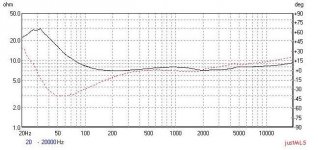
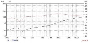
and this is impedanse of total speker mid-high plus bass. probbaly you will aunderstand now why I wanted to lower impedanse at mids.
thanks Andrew T and others for detailed answer. it will help me in future. seems in Loudspeakers forums are friendly helping people 
thanks Andrew T and others for detailed answer. it will help me in future. seems in Loudspeakers forums are friendly helping people
Attachments
It's ok to have the impedence 'all over the map'
A 16 ohm and a 2 ohm speaker can coexist happily.
The only consideration is whether your amp can drive the speakers.
In that case, you'd likely be raising the impedence because as I said,
Adding a parallel resistor will not effect what the speaker actually does.
Your goal should be equal sound pressure levels.
The speaker will receive the same voltage as before.
The speaker itself will draw the same current from the amp as before.
The added resistor will draw additional current based on V^2/R
The sound pressure level will be the same as before.
The frequency response of the speaker will remain the same as before.
All you will accomplish is to give the amplifier an extra load to provide power to. The amp will thus run hotter and be more burdened.
It may look good on paper. But it has on actual value.
my amps can drive anything including short circuit
with dedicated separated amps amps FR is flat.
however I tried my new power monoblocks pure class A which draws 24Amps (!) and dissipate 1200W idle. all the time, it happily drives 2ohms. with this amp bass ripp of the walls. but sound was somewhat in discinct to backward, I measured and find a litle bit 2-3db bass lift at 30-50hz ( I surprised as bass increasment listening to music looked like min 5-6db, trusting ears) and 7-20khz rolled off aproh 2-3db. I decreased L-pad to lift HF but hights seems the a litle bit blur no mater of increased level.
I am very surprised that impresive digits in reality does not works the same
the power delivered at 2 ohms region an 12ohms region should show spl 4-6db higher/lower but luckily this is not the case.
My experience of paralleling the woofer with a resistor in a passive crossover is that it can actually improve the sound quality, reducing colouration a fair amount in the crossover frequency region.
The reason for it working is that there's precious little electrical damping in a typical woofer LC crossover at the crossover frequency, as the L and C appear in parallel as a resonant circuit from the point of view of the woofer looking back at the amplifier output which can be thought of as a short circuit. I.E. the 'looking backwards' impedance can be several hundred ohms and so the woofer isn't damped hardly at all near the crossover region, but putting a resistor across it gives it some damping. The audible effect is reduced overhang, less muddle.
A suitable zobel should give nearly as good results with less effect on efficiency.
Adding a resistor in parallel has absolutely zero effect on the speaker.
It is a saparate and different path for curreny flow.
It only can effect amplifier output.
and only then for poor amplifier designs (or tube designs using a transformer.
Nothing will change this.
It's a separate, different circuit.
It is a saparate and different path for curreny flow.
It only can effect amplifier output.
and only then for poor amplifier designs (or tube designs using a transformer.
Nothing will change this.
It's a separate, different circuit.
myhrrhleine said:Adding a resistor in parallel has absolutely zero effect on the speaker.
It is a saparate and different path for curreny flow.
It only can effect amplifier output.
and only then for poor amplifier designs (or tube designs using a transformer.
Nothing will change this.
It's a separate, different circuit.
Sorry but you're not correct. You're just thinking about current coming out of the amplifier but a speaker is a generator of electricity when it moves, and damping it electrically exerts a braking effect, damping resonances in the cone. If you don't believe me just try tapping your finger on a woofer cone, listening to the sound it makes both with the terminals unconnected and then with them shorted out. There is a big difference with most woofers, shorting makes for a non resonant thud in comparison with open circuit and is a desirable thing to have generally speaking.
Therefore we should also be concerned with how a crossover and amplifier output looks impedance-wise in the reverse direction looking backwards from the woofer towards the amplifier. The impedances in each direction are not the same. It's a series L and parallel C 12dB/octave LP filter in the forward direction, but it's a parallel LCR network in the reverse direction as the woofer is now the generator and the amplifier is a short circuit. Parallel LCR networks have a high impedance at resonance, and in this case is the crossover frequency, so therefore there is no damping at the crossover frequency. In practice, due to losses mainly in the inductor, there is some damping but precious little really. A zobel helps, or a parallel resistor. It's the main reason active amps sound better, you get the full damping at all frequencies.
- Status
- This old topic is closed. If you want to reopen this topic, contact a moderator using the "Report Post" button.
- Home
- Loudspeakers
- Multi-Way
- what tradeoffs by lowering driver impedanse with resistor?