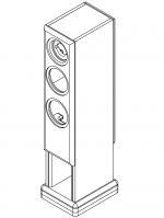
I'm building Zaph's Waveguide TMM, and cut the first pieces of wood today  .
.
The crossover I've chosen is the perfectionist crossover, but I don't understand how to connect the actual components, probably due to my near complete ignorance of all things electrical . The schematic shows a point labelled "IN" - is that the positive or negative connection from the amp? The "+" after the tweeter suggests to me that it's the negative connection. What do the earth connections on the schematic represent? The opposite connection to "IN" from the amp?
Finally I have some general crossover questions:
1) If an inductor's DCR does not match that specified in the schematic, should a resistor be added in the circuit after the inductor to bring the DCR up to that specified?
2) Are non-inductive wire-wound ceramic resistors suitable for crossovers?
Thanks for any advice you might give
.The crossover I've chosen is the perfectionist crossover, but I don't understand how to connect the actual components, probably due to my near complete ignorance of all things electrical
. The schematic shows a point labelled "IN" - is that the positive or negative connection from the amp? The "+" after the tweeter suggests to me that it's the negative connection. What do the earth connections on the schematic represent? The opposite connection to "IN" from the amp?Finally I have some general crossover questions:
1) If an inductor's DCR does not match that specified in the schematic, should a resistor be added in the circuit after the inductor to bring the DCR up to that specified?
2) Are non-inductive wire-wound ceramic resistors suitable for crossovers?
Thanks for any advice you might give
IN is the + (red) connection from the amplifier and all the earths connect together to the – (black) from the amplifier. The tweeter is in reverse phase so its + terminal is connected to earth. The woofer is normal phase so – connects to earth.
Adding a small resistor to an inductor is okay, but you’d be better off buying an inductor with the correct resistance (or close, say within 30%). Besides, the thicker gauge wire of a more expensive inductor would be wasted if you add a resistor in series, so save your money!
Non-inductive resistors are ideal for crossover work.
Good luck with your project!
Nice one,
David.
mikan said:Thanks David, that answered all my questions in one
Using a bigger inductor (in the right place) means your speakers will be more efficient. In your case, the difference is minimal, so you should be fine.
Dan
Adding the extra series resistance will help to ensure that your results are consistent with Zaph's. Naturally this is a good thing, however, it might be true that the lower DCR will sound better as this is often the case where the circuit location permits it.
Ideally I feel, it would be best if Zaph tweaked the crossover to suit your low DCR inductor. Practically speaking, I think you should try both and see which one you prefer.
Ideally I feel, it would be best if Zaph tweaked the crossover to suit your low DCR inductor. Practically speaking, I think you should try both and see which one you prefer.
lndm said:Practically speaking, I think you should try both and see which one you prefer. [/B]
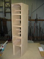
That's not a bad idea. The enclosures are mostly assembled now - only the bracing remains, then I'm up to making ports and adding the driver cutouts. I've changed the enclosures slightly so that the actual speakers sit on two stands which are the continuation of the sides (see the attached image) and the crossover is mounted in the base.
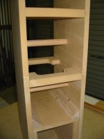
I've routed a 1/2" wide channel between the two panels of one of the legs on each enclosure using an R1/4" cove bit for passing the wires through. After gluing everything together, I realised that this channel will be too small to take 6x decent gauge wires and I should have routed at least two channels
.As a workaround, would it be OK to use 4x wires for the drivers all stuffed up this channel (3 for the "+" inputs, 1 for the "-" ground), or is it best if each driver has its own "-" wire? Will having so many wires crammed into such a small channel cause interference issues?
Attachments
I think this will be fine. If you are looking to take it further, you might consider bringing the three grounds down to one at a single point.mikan said:would it be OK to use 4x wires for the drivers all stuffed up this channel (3 for the "+" inputs, 1 for the "-" ground)
In a crossover? I would think probably not.Will having so many wires crammed into such a small channel cause interference issues?
lndm said:
I think this will be fine. If you are looking to take it further, you might consider bringing the three grounds down to one at a single point.
In a crossover? I would think probably not.
Sorry, I didn't explain that very well. The crossover is in the base, so the driver wires need to be passed up through the middle of one of the legs. The channel I've routed for this is only 1/2" wide, so the 4 driver wires (If i use a common driver ground wire) will be very close together. Will interference between the driver wires in this channel be a problem?
I think I understood you but I'll put it another way
Short answer: no.
There will be a small amount of mutual inductance and a small amount of capacitance between the cables. However, considering the frequencies involved, typical crossover impedances, and the lengths you mentioned, I would be very surprised if they caused any problems for your speaker.
My opinion would be that you should use the largest you can reasonably put in the channel, but don't try forcing it in or spending huge amounts on it.
I think it is more important to have clean connections.
To put a fine point on it, and some may have differing opinions here (and some may think the difference is negligible), you might use a heavier guage for the ground return to the crossover.
I think that multi strand versus single strand may not matter at audio frequencies, but single strand may break with the vibrations.
I think it is more important to have clean connections.
Would perhaps 4x heavier core wire be better? Single core or multi strand?
To put a fine point on it, and some may have differing opinions here (and some may think the difference is negligible), you might use a heavier guage for the ground return to the crossover.
I think that multi strand versus single strand may not matter at audio frequencies, but single strand may break with the vibrations.
paulspencer said:How's it going? I have been experimenting with waveguides myself, so I'm curios to hear about this one.
The cabinets are complete except for some additional bracing, internal wiring and stuffing. When modifying the waveguides, I found I had to take the internal hole to 41.0mm to prevent the WG from overhanging the radius on the tweeter. I can't finish the base and baffles until I have veneered the sides and top. Time has run out for working on the speakers, so I won't have them finished until late July
. I'll post an update when they're done.BobEllis said:mikan,
just as you can parallel caps to reach the value you need, you can also parallel resistors. Need a 0R1? parallel 5 0R5 3Ws and you have a 15W 0R1. (As long as you give them all some room for air to circulate)
Thanks Bob, I didn't realise the power handling scaled. That makes finding suitable resistors easy
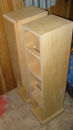
Baffles on one of the boxes, no cutouts yet and the edges have not been sanded to fit. The iron-on veneer (Radiata Pine, which is classified as a weed in parts of Australia) is also not sanded or lacquered yet. The bases are not yet attached. The bases and baffles will be sprayed in wrinkle finish black, and the veneer will be finished with clear acrylic lacquer.
Attachments
- Status
- This old topic is closed. If you want to reopen this topic, contact a moderator using the "Report Post" button.
- Home
- Loudspeakers
- Multi-Way
- Understanding the Zaph Waveguide TMM crossover diagram