Cortez said:Yes, its clear now, thank you !
And why is the bottom end shorted with that wall down there ?
Or this is: "The lower camber is to adsorption a frequency at 200Hz." ?
I have a 10" driver:
http://www.d-s-t.com/link/vifa/data/m25wo-49-08e.htm
Do you think it would be appropriate for a TML ?
Hi
sorry wrong datas
will edit them this evening

Hi @ll
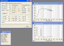
I have had a friend at my home with a measurement system.
TML pure (without X-over)
Fullrange speaker pure
I have got a room-problem with 90Hz and 120Hz as you can see at both measurings.
The complete system:
The W300A-II has a 12mH coil. The Coral 8A70 is runing full.
I have had a friend at my home with a measurement system.
TML pure (without X-over)
An externally hosted image should be here but it was not working when we last tested it.
Fullrange speaker pure
An externally hosted image should be here but it was not working when we last tested it.
I have got a room-problem with 90Hz and 120Hz as you can see at both measurings.
The complete system:
The W300A-II has a 12mH coil. The Coral 8A70 is runing full.
An externally hosted image should be here but it was not working when we last tested it.
Roemhild said:the "normal" design is that you use the surface area [Sd] from the driver for the opening area [Am]. The staring area [Ah] from the TML is 1.5 ... 2.0 times larger.
I sure hope no one does it that way any longer. That is now referred to as classic design and has been shown to be hit or miss -- mostly miss. Sd actually has nothing to do with the end volume of an optimal line.
If you want the best TL possible, seeing how it does in Martin King's TL worksheets is the way to go... i'm stronly suspecting that that the box volume you have for your TL is smaller then optimum, and that more careful positioning of the driver in the line would help reduce ripple. 1/3 is a good starting point but probably not optimum (depends on the taper ratio).
Basee response only into the 50s and measured ripple of +/- 5 dB tends to support the above (but without knowing the room contribution...)
Because your line is tapered formula 4 is incorrect. The quarter-wave resonance in a tapered line is lower than what is calculated by wl/4.
dave
Hi Dave,
thx for your post it means a lot to me. I respect your work and your knowlage
Hope I get things right (my technical english ain`t the best)
Ok of course I know that the formulas are a really simple and easy way.
The MK-sheet is one way to calculate a TML. I just tried a new way and shared it. I have reduced the volume after I have build up my TML. And it was really interesting what happend. Have you ever played with a volume of a speaker? I mean reduced it until you have heared 500ml difference?
I don`t understand what you mean and what it wrong with the formula.
best regards Till
thx for your post it means a lot to me. I respect your work and your knowlage
Hope I get things right (my technical english ain`t the best)
planet10 said:
I sure hope no one does it that way any longer. That is now referred to as classic design and has been shown to be hit or miss -- mostly miss. Sd actually has nothing to do with the end volume of an optimal line.
Ok of course I know that the formulas are a really simple and easy way.
planet10 said:
If you want the best TL possible, seeing how it does in Martin King's TL worksheets is the way to go... i'm stronly suspecting that that the box volume you have for your TL is smaller then optimum, and that more careful positioning of the driver in the line would help reduce ripple. 1/3 is a good starting point but probably not optimum (depends on the taper ratio).
The MK-sheet is one way to calculate a TML. I just tried a new way and shared it. I have reduced the volume after I have build up my TML. And it was really interesting what happend. Have you ever played with a volume of a speaker? I mean reduced it until you have heared 500ml difference?
planet10 said:
Basee response only into the 50s and measured ripple of +/- 5 dB tends to support the above (but without knowing the room contribution...)
Because your line is tapered formula 4 is incorrect. The quarter-wave resonance in a tapered line is lower than what is calculated by wl/4.
dave
I don`t understand what you mean and what it wrong with the formula.
best regards Till
Roemhild said:I don`t understand what you mean and what it wrong with the formula.
That formula is only valid for a 1/4 wave line where the closed end has the same area as the open end (ie a straight pipe). If the closed end is larger than the open end (yours) the pipe has to be shorter for the same primamry resonance. If the closed end is smaller than the open end (voigt) then the line has to be longer.
dave
planet10 said:
That formula is only valid for a 1/4 wave line where the closed end has the same area as the open end (ie a straight pipe). If the closed end is larger than the open end (yours) the pipe has to be shorter for the same primamry resonance. If the closed end is smaller than the open end (voigt) then the line has to be longer.
dave
Good morning Dave,
I don`t see it this way. I have tried some different ways. I have had the TML also longer but I have had the best results with this way.
And As you can see on the simulation and the measuring the result is what I have expected
simulation
An externally hosted image should be here but it was not working when we last tested it.
measurement
An externally hosted image should be here but it was not working when we last tested it.
I know that I have a problem with two room frequencys.
Maybe you could try it out yourselve
best wish
Till
Roemhild,
I'm not saying your design is wrong, or that it doesn't work. I'm just saying the 1 formula is wrong. That is well estabished.
Because your line is not tapered much, and because you are choosing a line length between a straight pipe 1/4 wave & the BR tuning you are still shorter the Fs/4 but not by as much as your math tells you.
It is also fairly well established that tuning higher than Fs/4 you get more quantity but not as much extension, quite often a useful tradeoff.
dave
planet10 said:Roemhild,
I'm not saying your design is wrong, or that it doesn't work. I'm just saying the 1 formula is wrong. That is well estabished.
Hi Dave
ok I think I get the knowlege of your point of view.
planet10 said:
Because your line is not tapered much, and because you are choosing a line length between a straight pipe 1/4 wave & the BR tuning you are still shorter the Fs/4 but not by as much as your math tells you.
It is also fairly well established that tuning higher than Fs/4 you get more quantity but not as much extension, quite often a useful tradeoff.
dave
How would you calculate the lenght than?
best regards Till
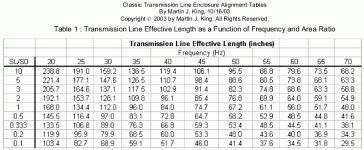
Roemhild said:How would you calculate the lenght than?
I don't know if there is a closed-form formula. It falls out when you are modeling in MJK, or to get a ballpark when i'm sketching, i use the table in Martin's alignment tables (available at his web site )
Table 1 is reproduced below.
dave
Attachments
- Status
- This old topic is closed. If you want to reopen this topic, contact a moderator using the "Report Post" button.
- Home
- Loudspeakers
- Multi-Way
- my new way to build a TML