I will suppose that something like this isn't possible when power amplifiers are under test.Hi, MagicBus
if you put preamp in loopback, the you have to decouple preamplifier Input / output ground, as I do in ARTA box. Practically, do not connect ground on input channel.
ARTA can't make hum.
Best,
Ivo
Every Time i tried this i see a smoked zobel
Last edited:
thanks IvoValtergio,
please test souncard response in loopback mode.
If you get 10kHz filtered response then you have bad souncard.
If you get wideband response, then you have problem in your amplifier.
Ivo
test soundcard loop mode.
is right?
The Amplifier work fine, i hear the high frequency very well.
Attachments
I will suppose that something like this isn't possible when power amplifiers are under test.
Every Time i tried this i see a smoked zobel
You can put power amplifier in loopback, but not directly. You must set resistive voltage divider (i.e 50:1) at ampifier output, to protect soundcard input.
Ivo
thanks Ivo
test soundcard loop mode.
is right?
The Amplifier work fine, i hear the high frequency very well.
Now you have to test your microphone and its preamplifier.
Ivo
Now you have to test your microphone and its preamplifier.
Ivo
For the mic i have not possibility to test it, i should to buy it,
thus i will to consider how the last option when i am sure that the rest is ok.
For pre mic testing,
do i can insert it in the loop cable test?
if yes, Perhaps i will need it to reduce-adapt the signal level whit a potenziometer?
Thanks for answer,yes i have done this many times but my question is about disconnected input gnd.You can put power amplifier in loopback, but not directly. You must set resistive voltage divider (i.e 50:1) at ampifier output, to protect soundcard input.
Ivo
Thanks for answer,yes i have done this many times but my question is about disconnected input gnd.
Without knowing the specifics of your power amplifier internals, it's not possible to know whether a disconnected input ground would cause an issue.
In your case, obviously it is, so there is some investigation required for your power-amp/soundcard interface.
Dave.
Hi, MagicBus
if you put preamp in loopback, the you have to decouple preamplifier Input / output ground, as I do in ARTA box. Practically, do not connect ground on input channel.
ARTA can't make hum.
Best,
Ivo
I've found the best solution to the problem of ground loops when measuring the output of a power amplifier or passive crossover is to use audio transformer isolation.Yes, I've tried this and much more workaround for ground loops. I keep that it can't be software related and from there on I'll fix it. Thank you very much!
I have a small can shaped audio transformer maybe 40mm long and 20mm wide with two windings and a number of taps.
I connect the highest impedance primary winding (3k ohm or 6k ohm - can't quite remember) to the device under test and the lowest impedance tap on the secondary (300 ohms - centre tap to one side of a 600 ohm winding) directly to the line input of the sound card.
This has many advantages:
1) Full galvanic isolation and no ground loops at all, which makes it possible to measure the slope of a high/low pass filter right down to the sound cards noise floor. (Normally ground loops will give a false inflexion point as little as 40-50dB down as out of phase ground currents predominate)
2) Complete freedom to do measurements that are not ground referenced - such as differential measurements between two crossover outputs, measurements across drivers in series crossovers etc. This can be very useful.
3) The impedance step down ratio of the transformer steps the maximum voltage from a 100W amplifier down to a safe level for a normal line input without any L-Pad being required. (as long as you have at least a 20/1 voltage step down ratio)
4) The impedance ratio of the transformer when connected to a typical passive crossover under test reflects a very low source impedance into the line in on the sound card, which means frequency response variations due to the input impedance of the sound card not being flat are avoided, whereas a high resistance L-Pad will be very sensitive to variations in the sound cards input impedance.
5) The typical 10k input impedance of a line input is multiplied by the impedance ratio of the transformer so the device under test sees a load impedance of over 100k for example. (Except at very low frequencies below a few Hz)
Of course the transformer has the possibility to be overloaded introducing distortion or introduce frequency response variations of its own, so it needs to be carefully selected, and needs to have its response measured to make sure it is not causing measurement errors.
However the particular transformer I use is ruler flat from about 5Hz to nearly 50Khz - and in practice it would be flatter in response than using an L-Pad which would allow line in impedance variations to affect the frequency response. Measured distortion is also vanishingly low, and is low enough to actually measure the distortion of a power amplifier accurately.
I've had excellent results using this transformer to measure the output of power amplifiers and passive crossovers.
Last edited:
I've found the best solution to the problem of ground loops when measuring the output of a power amplifier or passive crossover is to use audio transformer isolation.
I have a small can shaped audio transformer maybe 40mm long and 20mm wide with two windings and a number of taps.
I connect the highest impedance primary winding (3k ohm or 6k ohm - can't quite remember) to the device under test and the lowest impedance tap on the secondary (300 ohms - centre tap to one side of a 600 ohm winding) directly to the line input of the sound card.
This has many advantages:
1) Full galvanic isolation and no ground loops at all, which makes it possible to measure the slope of a high/low pass filter right down to the sound cards noise floor. (Normally ground loops will give a false inflexion point as little as 40-50dB down as out of phase ground currents predominate)
2) Complete freedom to do measurements that are not ground referenced - such as differential measurements between two crossover outputs, measurements across drivers in series crossovers etc. This can be very useful.
3) The impedance step down ratio of the transformer steps the maximum voltage from a 100W amplifier down to a safe level for a normal line input without any L-Pad being required. (as long as you have at least a 20/1 voltage step down ratio)
4) The impedance ratio of the transformer when connected to a typical passive crossover under test reflects a very low source impedance into the line in on the sound card, which means frequency response variations due to the input impedance of the sound card not being flat are avoided, whereas a high resistance L-Pad will be very sensitive to variations in the sound cards input impedance.
5) The typical 10k input impedance of a line input is multiplied by the impedance ratio of the transformer so the device under test sees a load impedance of over 100k for example. (Except at very low frequencies below a few Hz)
Of course the transformer has the possibility to be overloaded introducing distortion or introduce frequency response variations of its own, so it needs to be carefully selected, and needs to have its response measured to make sure it is not causing measurement errors.
However the particular transformer I use is ruler flat from about 5Hz to nearly 50Khz - and in practice it would be flatter in response than using an L-Pad which would allow line in impedance variations to affect the frequency response. Measured distortion is also vanishingly low, and is low enough to actually measure the distortion of a power amplifier accurately.
I've had excellent results using this transformer to measure the output of power amplifiers and passive crossovers.
could you publish a circuit?
thank you
There really isn't any circuit to publish.could you publish a circuit?
thank you
")
The primary high impedance winding of the transformer connects to the circuit under test such as an in-use passive crossover, and the lowest impedance secondary winding connects directly to the sound card line input left and ground.
The key to making it work is to use the right transformer that has the impedance step down ratio needed and has a very flat frequency response and low distortion.
I lucked out with the transformer I'm using - it came out of my Dad's parts bin years ago so I have no idea what it originally belonged to - it's quite possible that it came out of a valve pre-amp, as it looks to be of that era.
I've just dug out the transformer in question and wanted to correct the record on the impedance of the windings, which are not quite what I thought.
The primary is 1.2k ohms and I am using the 30 ohm secondary tap to go to the line input of the sound card - which is an impedance step down ratio of 40 to 1.
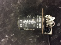
I see on the can that it was made by Nihon Kohden and appears to date to 1969. Anyone recognise what equipment it is out of ? It sure works well in this application.
It looks from the diagram that it has a Faraday shield between primary and secondary as well - although I'm not using that as I don't have the screw on the bottom of the case earthed, but I could easily do so.
The primary is 1.2k ohms and I am using the 30 ohm secondary tap to go to the line input of the sound card - which is an impedance step down ratio of 40 to 1.
I see on the can that it was made by Nihon Kohden and appears to date to 1969.
Anyone recognise what equipment it is out of ? It sure works well in this application.It looks from the diagram that it has a Faraday shield between primary and secondary as well - although I'm not using that as I don't have the screw on the bottom of the case earthed, but I could easily do so.
Attachments
Last edited:
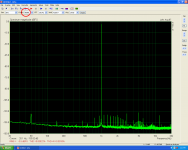
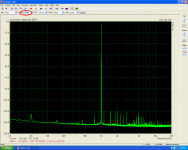
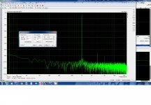
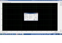
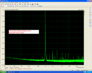
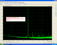
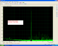
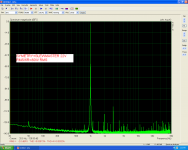
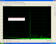
Some real measurements using Esi Julia pci.
1,2,3 Symetry+Slewmaster amplifier
4,5 Wolverine+Slewmaster amplifier.
1,2,3 Symetry+Slewmaster amplifier
4,5 Wolverine+Slewmaster amplifier.
Attachments
Last edited:
None of those have a sufficient step down ratio - the highest one I see there is 10:1, you really need about 40:1 at a minimum to keep the voltage to a safe level on the sound card input without additional protection circuitry being required.
If your signal source is an amplifier rated to 100W in 8 ohms that is about 28.2v RMS maximum, a 40:1 ratio will reduce that to 0.7v RMS which is a safe value below clipping for most consumer grade sound card line inputs which are rated to -4dBu. (Pro gear can usually go to +10dBu so has more headroom before clipping)
There really isn't any circuit to publish.
The primary high impedance winding of the transformer connects to the circuit under test such as an in-use passive crossover, and the lowest impedance secondary winding connects directly to the sound card line input left and ground.
The key to making it work is to use the right transformer that has the impedance step down ratio needed and has a very flat frequency response and low distortion.
I lucked out with the transformer I'm using - it came out of my Dad's parts bin years ago so I have no idea what it originally belonged to - it's quite possible that it came out of a valve pre-amp, as it looks to be of that era.
Ok, so I will replace the voltage divider with the transformer?
Hi rich08,
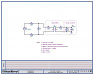
Of the list of Neutrix transformers that Aczern cited, I think the NTL1 would be my best choice simply because its rated maximum input level at 50Hz /1% THD being +19dBu.
At 20Hz, the THD at levels common to computer sound card inputs should therefore be very low. Since the turns ratio is 1:1, an input attenuator will be necessary if testing of high power audio amplifiers is required.
I haven’t actually tried this transformer but simulations on the circuit shown attached shows good performance. Hope this helps.
Peter
Attachments
Hi rich08,
Of the list of Neutrix transformers that Aczern cited, I think the NTL1 would be my best choice simply because its rated maximum input level at 50Hz /1% THD being +19dBu.
At 20Hz, the THD at levels common to computer sound card inputs should therefore be very low. Since the turns ratio is 1:1, an input attenuator will be necessary if testing of high power audio amplifiers is required.
I haven’t actually tried this transformer but simulations on the circuit shown attached shows good performance. Hope this helps.
Peter
Thank you Peter