The cable resistance/impedance can easily be compensated with a 4-wire measuring method.How would that help? Under normal situation, a driver is connected to the amplifier via a crossover circuit which has a resistance and on top some reactive impedance (inductor, capacitor). Just the resistance is -including the cable - easily 1 Ohm or more.
Although in ARTA this can be manually be compensated as well (as mentioned just a couple of posts back)
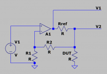
Here a global schematic with a constant voltage source with ref resistor.
Crossovers etc are not part of this story, since they are obviously the DUT.
We were talking about measuring loudspeaker impedances, not crossovers.
Attachments
Member
Joined 2003
Yeah, some days my brain just ain't right. Low value sense resistor, constant voltage. High value sense resistor, constant current. However, very small sense resistor will make for smaller measurement amplitude, so decreased resolution unless signal is fairly large.For a more constant voltage across the driver you need the lowest possible sense resistor and a source with very low output impedance (i.e. an amplifier).
I don't understand the benefit of placing a resistor inside the feedback loop of the amplifier, and I've no interest in building a special amplifier just for measuring impedance and T/S. In any case, high value sense resistor may make more sense to provide a signal to the driver that is closer to what it will see when directly connected to the amp. I'll see if I have anything lying around, can always do a quick comparison of small sense R to large sense R if there is any meaningful difference in measured results.
and @DcibeLMy apologies, let me rephrase my question. How accurate has the driver impedance measurement to be? And if so why?
It's not about how accurate the measuring setup is.
It's how the driver will respond to a certain signal.
Fact is that with a divider network, the voltage on the terminals will differ significantly depending on the frequency (aka impedance of the speaker)
For measuring impedance for a crossover this is not really a big deal.
For determining T/S parameters, this will be a big deal, since the voltage across the frequency range isn't constant anymore.
Actually, using a stepped sine wave compared to a pink noise already gives an extremely significant change.
When determining T/S parameters one wants to at least verify the manufacture's claimed parameters (under the same conditions manufactures measure these).
Since most manufactures don't comply with AES standards (eg measuring higher voltage), this is worth double checking.
It's also worth translating this to AES standards, which means measuring at 0.1V and with a constant voltage source.
The divider network isn't a constant voltage source, very far from it actually.
The benefit of placing the resistor inside the voltage loop will provide a constant voltage on the speaker terminals.
Yet, still give the option of measuring it ARTA (LIMP) as before.
So constant voltage over constant current basically. To my knowledge f.i. is ScanSpeak using the constant current approach.
In a passive crossover situation at low frequencies there is about 1ohm in series with the bass driver Fed nu a constant voltage amplifier. Would a measurement with 1 Ohm reference resistor in series not be better, as it is close to the actual situation with a passive crossover?
In a passive crossover situation at low frequencies there is about 1ohm in series with the bass driver Fed nu a constant voltage amplifier. Would a measurement with 1 Ohm reference resistor in series not be better, as it is close to the actual situation with a passive crossover?
Either constant voltage or constant current would be fine I think, as long as that's a constant parameter.So constant voltage over constant current basically. To my knowledge f.i. is ScanSpeak using the constant current approach.
In a passive crossover situation at low frequencies there is about 1ohm in series with the bass driver Fed nu a constant voltage amplifier. Would a measurement with 1 Ohm reference resistor in series not be better, as it is close to the actual situation with a passive crossover?
Which it isn't with the divider method.
There are some advantages and disadvantages for both.
fyi, I am oversimplifying things by saying "T/S parameters".
It's more about predicting certain speaker behavior around the Fs
Member
Joined 2003
Consideration for the implementation of a crossover is irrelevant. The result of the impedance sweep is T/S, which we should know can vary in result depending on drive voltage applied, and T/S is intended to be parameters of the speaker "at rest" so it is low level by definition.
What matters is, does the cabinet model differ in any amount when the T/S are determined by some "constant voltage" method, or by voltage divider where voltage at the driver varies with frequency. I've a feeling we may be splitting hairs, as my cabinets designed around T/S determined by voltage divider method are not awful messes.
The largest resistor I found in my stash is 180 ohm, so I can certainly compare the T/S result and cabinet model of a speaker measured using voltage divider of 10 ohm vs 180 ohm. Is it worth the time and effort ?
Well that used to be my way of thinking as well. Until I recently bumped into an issue with a couple of datasheets.Consideration for the implementation of a crossover is irrelevant. The result of the impedance sweep is T/S, which we should know can vary in result depending on drive voltage applied, and T/S is intended to be parameters of the speaker "at rest" so it is low level by definition.
What matters is, does the cabinet model differ in any amount when the T/S are determined by some "constant voltage" method, or by voltage divider where voltage at the driver varies with frequency. I've a feeling we may be splitting hairs, as my cabinets designed around T/S determined by voltage divider method are not awful messes.
The largest resistor I found in my stash is 180 ohm, so I can certainly compare the T/S result and cabinet model of a speaker measured using voltage divider of 10 ohm vs 180 ohm. Is it worth the time and effort ?
My own measurements were way off, or so I thought.
After emailing back and forth with the manufacturer, I basically ended up in a chicken-egg debate.
The worrying part is that I see more manufacturers doing the same thing.
With a constant voltage source I can replicate the datasheet numbers as well as being compliant to AES standards.
Besides, like I said it's much more than just T/S parameters as well. See it as a very simple Klippel setup.
With a constant voltage source one can actually get a good sense of how much the Fs is shifting (mostly because of the compliance). With the constant current method one can measure the distortion of the motor (Hificompass is doing this for example).
All this can help in the design.
In cases it's actually essential to know these thing.
Member
Joined 2003
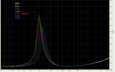
If it interests anyone, the difference in impedance sweep result between using a 10 ohm sense resistor and 190 ohm sense resistor is pretty much zilch. If anything, very small increase in the impedance peak amplitude, so it wil have very slightly lower Qms at 10 ohm test, but not enough to care about, certainly no change in Fs given about the same signal amplitude. So I'm just going to keep on with my 10 ohm voltage divider method.
Too many people focus on comparing their measurement to the datasheet, with exclamations that the manufacturer has given them a dud, the datasheet is wrong, etc...but without comparing the resulting cabinet model, or understanding of what difference in T/S parameters means. Last time I saw these claims, I did this person a favour and modelled the driver in a cabinet using his measurement vs the datasheet. Result clearly showed the driver was performing perfectly as advertised.
In any case, this is going a bit OT for ARTA/LIMP discussion, as the program can accommodate whatever testing method you wish.
Member
Joined 2003
Ehm , yes crest factor of pink noise is very different.Would it matter PN or sine ? Voltage is voltage
Here's comparison of stepped sine, yellow = 10 ohm, green = 190 ohm, never mind the wiggle at 25Hz that was my fault, otherwise I would say the difference is not enough to care about.
View attachment 1024223
What output voltage was that?
Because with pink noise vs sine wave at same output gain I always see a noticeable shift in Fs.
Also, what speaker is this?
Because this effect won't be noticeable at all with very linear speakers obviously.
Kind of pointless to show the change of compliance in a very well performing speaker.
I already showed it somewhere else, but when I am back home again I will show some measurements I did with a bunch of 4 inch woofers as well as the result from the manufacturer.
Sort of compares with my quick test. Using Arta-limp with headphone output of scarlett2i2-2th with 100 or 50 ohms matches with amplifier and 27 ohm tests some years earlier. (On tweeter and midrange) The voltage used makes a difference when measuring capacitors and resistors because of noise apparently. Also for the lead compensation.
Coming week i will test als with amplifier and woofers, will also reduce the resistor to see the effects. I use only sealed box for woofers. May be that is less sensitive for t/s variations.
Coming week i will test als with amplifier and woofers, will also reduce the resistor to see the effects. I use only sealed box for woofers. May be that is less sensitive for t/s variations.
Member
Joined 2003
What about crest factor? I am measuring impedance, output amplitude set the same, only difference is size of sensing resistor. For comparison, the change in result will not be different. Resulting T/S parameters may be different between PN and sine simply due to drive level, but did it affect the cabinet model?Ehm , yes crest factor of pink noise is very different.
What output voltage was that?
Because with pink noise vs sine wave at same output gain I always see a noticeable shift in Fs.
Also, what speaker is this?
Because this effect won't be noticeable at all with very linear speakers obviously.
Kind of pointless to show the change of compliance in a very well performing speaker.
I already showed it somewhere else, but when I am back home again I will show some measurements I did with a bunch of 4 inch woofers as well as the result from the manufacturer.
I am measuring impedance for T/S, which are defined as "at rest" conditions, so voltage should be low, only about 250mVrms here. I know you are about to say I need 1V or 2V, that may give you some useful information on the driver, but I would disagree on that voltage for T/S whether some other manufacturer does it or not.
Again, focus is on single parameter, Fs. I'm sure that Fs wasn't the only parameter to change. What of the box model with other parameters included, did it change significantly? The differences observed from this constant voltage vs voltage divider are quite simply put as difference in drive voltage, at Fs particularly. I should have gone a bit more in-depth with my test above and completed full T/S and modelled the cabinet, but I've already determined in the past that the model is not different enough to care about. Perhaps we have different goals, as I am only trying to determine accurate parameters to model a cabinet that matches reality when I built it.
I don't have interest in matching the datasheet, sort of the point of measuring myself is to throw away the datasheet, they are often unreliable. We've also determined clearly, that the T/S parameter results differ from many factors such as drive level, constant voltage vs voltage divider, ambient temperature, break in vs new, etc.
As a simple test, run impedance sweep using PN noise and no averaging, then adjust the gain of your amp and watch Fs change over amplitude. Which Fs is "correct" ? There isn't a well defined standard so manufacturers can do whatever results in the most marketable specs which is just another reason to put little trust in manufacturer data.
Of course, the speaker tested above was a good one. I don't have much interest in building low end speakers
")
Last edited:
When i was stille active in producing systems, i used the t/s data primarely to select for fc and for woofers for use in sealed box.
Then order and test. To day still surprised how noisy f.i. a spider can be.
The cone behaviour (dimensions, breakup) then was the determining factor.
Then order and test. To day still surprised how noisy f.i. a spider can be.
The cone behaviour (dimensions, breakup) then was the determining factor.
Member
Joined 2003
Simple comparison of different drive voltage. Here, a cheap 3" TB fullrange driver was used, no copper in the motor I am sure.
Measured complete T/S using 250mV drive voltage, and again at 1.5V, using voltage divider and 10 ohm resistor.
At elevated voltage, Fs is indeed lower, nearly 5Hz difference, as well Qts is lower, Cms higher, Vas higher, BL slightly lower. End result, cabinet simulation is pretty much exactly the same. Although, the T/S parameters at elevated voltage may look more favourable on a datasheet.
@DcibeL
The whole point of measuring any at all, is to predict what and how a speaker is going to behave.
Not just on (super) low signal levels, but in an environment the speaker is being used for.
Second to that, is to get a decent feeling of how certain datasheets can be interpreted before spending those hard earned dollars, or in some cases to give other people advice beforehand.
I find just "quick and dirty" one off measurements completely useless.
They don't hold any scientific value, and/or extremely little engineering value.
You might not even do it to begin with, before claiming datasheets are "false" since they don't hold any value.
The reason why, is because it all depends.
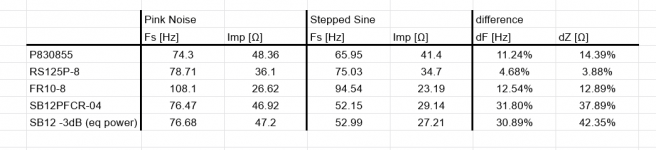
Here you can see a table with a couple of 4 inch woofers I tested a while ago.
Plus a measurements of a VERY reputable and respected brand (can't exactly tell which one unfortunately, I wish I could)
What does it show us?
Well how linear the speaker is really, (or the compliance)
In case of the speaker of the manufacture, this was actually VERY audible when the speaker was being played at small signal levels (a little more than just background music).
Klippel measurements aren't available, yet people still want to create nice speaker projects (for whatever reason).
In this case, someone was heavily disappointing by the outcome.
I say it again, it's NOT just about T/S parameters (which you keep referring back to).
It's all about getting useful data to get predictable results.
Showing a very well made speaker with some quick and dirty measurements is kind of showing the obviously.
Even more so when Klippel measurements are known and show they are super linear.
Why would you do a measurement in the first place?
Seen in the table is the Fs, with the impedance peak (I could have given the Qts, which is proportional to) from a PN signal vs stepped sine wave at the same gain level output as well as equivalent compensated output for the pink noise to sine wave level.
Some of the results fall into errors/tolerances that can be expected, around 10% or thereabouts.
But there are some that go towards 30-40% !!!
The whole point of measuring any at all, is to predict what and how a speaker is going to behave.
Not just on (super) low signal levels, but in an environment the speaker is being used for.
Second to that, is to get a decent feeling of how certain datasheets can be interpreted before spending those hard earned dollars, or in some cases to give other people advice beforehand.
I find just "quick and dirty" one off measurements completely useless.
They don't hold any scientific value, and/or extremely little engineering value.
You might not even do it to begin with, before claiming datasheets are "false" since they don't hold any value.
The reason why, is because it all depends.
Here you can see a table with a couple of 4 inch woofers I tested a while ago.
Plus a measurements of a VERY reputable and respected brand (can't exactly tell which one unfortunately, I wish I could)
What does it show us?
Well how linear the speaker is really, (or the compliance)
In case of the speaker of the manufacture, this was actually VERY audible when the speaker was being played at small signal levels (a little more than just background music).
Klippel measurements aren't available, yet people still want to create nice speaker projects (for whatever reason).
In this case, someone was heavily disappointing by the outcome.
I say it again, it's NOT just about T/S parameters (which you keep referring back to).
It's all about getting useful data to get predictable results.
Showing a very well made speaker with some quick and dirty measurements is kind of showing the obviously.
Even more so when Klippel measurements are known and show they are super linear.
Why would you do a measurement in the first place?
Seen in the table is the Fs, with the impedance peak (I could have given the Qts, which is proportional to) from a PN signal vs stepped sine wave at the same gain level output as well as equivalent compensated output for the pink noise to sine wave level.
Some of the results fall into errors/tolerances that can be expected, around 10% or thereabouts.
But there are some that go towards 30-40% !!!
Attachments
Member
Joined 2003
That's all fine and dandy if you are an design engineer working for a business, or making comparison of many drivers like HifiCompass for example. Myself as a DIYer, have already made my choice and purchased a driver with intent to use it and enjoy it, so this compliance stuff is more just nice to know, tell me how it affects your design using that driver? I focus on T/S because that is the input data to my cabinet design. I think I mentioned before, that we seem to have different goals in mind here.
That said, your comparison of SB drivers is quite staggering. However you mention "same gain level output", which you previously noted something about crest factor, so was the comparison made simply a matter of drive voltage vs frequency? Comparing rms level of a wide spectrum signal vs a sine signal will not do the trick. I ran some quick test, and found about 15dB of attenuation of the sine will match up with the PN noise, given the 3" fullrange driver I tested above. I am in full agreement that a sine sweep is a better stimulus for impedance, it is just an easier signal to analyze.
Again, the only difference whether PN noise, sine, voltage divider constant voltage, is drive voltage at any given frequency. The same comparison you've made above can be completed using a voltage divider, it is only a bit more complicated to determine the voltage at the driver, placing a multimeter at the amp output won't do the trick for a voltage divider, so measure at the driver with sine signal at Fs.
@DcibeL
Well actually, the whole example came to light from another DIY friend who ran into audible issues as well.
So it does actually also apply to DIY projects, not only professional work and I think it's a lot more valuable instead of "just nice to know".
In his case he was getting fed up by the fact why his impedance measurements didn't show what was being expected from the datasheet. But also why soft playing sounded so much more terrible as decent volume playing (with that I don't mean loud)
What I meant with "same gain level output" in simple words; just the volume knob at the same position.
Which isn't the same, I know, but it was just to illustrate how much difference there can be.
(which isn't obvious for a lot of DIY'ers as well as professionals)
Not to mention that those low voltage line-level (heavily overpriced) sound-card devices are completely useless.
If you mention cabinet design, you also have to think about how the driver in question is going to be used.
Is that at higher SPL levels, or just background music etc etc etc?
The issue with a divider is that the voltage is just not constant over the loudspeaker terminals.
So by definition the measured output won't be linear, since the driver is not behaving on the same way at different frequencies. Which results to some kind of self centering kind of behavior.
With a constant voltage it does.
Member
Joined 2003
@DcibeL
Not to mention that those low voltage line-level (heavily overpriced) sound-card devices are completely useless.
Sure, anyone can attach a resistor to some wire and get the same result. It is just a cheap USB codec with a resistor built in after all, but someone might want a paycheque to write software, design, document, manufacture, distribute, market. Most people just want T/S to design a cabinet, is it still useless for that?
If you mention cabinet design, you also have to think about how the driver in question is going to be used.
Is that at higher SPL levels, or just background music etc etc etc?
Just crank it up, what's the problem?