Hey Guys and Gals,
I have a few questions, I'm sure they have been answered somewhere in this thread, but after a bunch of searching, I can't seem to find what I am looking for.
First, I am assuming that for the amplifier gain setting under Audio Devices is gain and NOT gain in dB. My amp is rated at 26dB of gain which gives me 19.95 if my feeble math skills are correct?
Second, I am using a Steinburg UR22mk2. This is calibrated and is giving me correct readings when I have things set up in loop back. The question is about pre-amp gain for the microphone. Do I still have to put a figure in or has that already been accounted for during the calibration process? Since the input sensitivity has already been set...would that not already include pre-amp gain?
Thanks,
Erik
Not to double post, but I found this on another forum about the Steinburg:
"No, preamps at UR22 aren't bypassable. Signal is always going through preamps, although TRS jacks in the center of combo connectors are adapted for line level signals.
That means also different clipping point (maximum analog level mapped to digital zero). For MIC (XLR) input it is -6dBu and for LINE (TRS) input it is +14dBu."
So I guess that would mean if I'm using the TRS input then I would enter 10^(-6/20)=0.5011 and if I would be using the XLR input then 10^(14/20)=5.011 for preamp gain?
I calibrated everything using the TRS inputs on the front, but I suppose if my gain setting is correct than it shouldn't really matter as long as I correct it if I change input connection style?
Thank you,
Erik
Diode Calculations
OK,
Been building speakers for almost 2 decades and I feel pretty confident with doing so and what I have produced and measured. Now, as I was looking at the Measuring Jig in the ARTA manual that I have faithfully used for many years, I began to wonder how the diode values were arrived at.
Here I am likely showing my diodic ignorance😉. 4.1 volts is more than one might want a sound card to handle though my logic is likely off here (and is not a common value so how would one arrive at a rationale to go to 3.9 or 4.3?). What is the method to calculate the needed diode value in the circuit for the ARTA Measuring Box?
Thanks in advance.
The diode turn on voltage needs to be significantly higher than the maximum expected signal voltage as diodes don't have an infinitely sharp knee. If their turn on voltage is too close to the signal voltage they will start to introduce distortion due to drawing some non-linear current through the series resistor as they start to conduct slightly.
On the other hand they need to be low enough in voltage that they keep the voltage below what will actually cause irreversible harm to the input circuit. They're not there to avoid clipping below 0dBFS, they're there to prevent damage.
On the other hand they need to be low enough in voltage that they keep the voltage below what will actually cause irreversible harm to the input circuit. They're not there to avoid clipping below 0dBFS, they're there to prevent damage.
Thanks DBMandrake. I have a Scarlett 4i4 and from what I can tell,
Maximum Input Level
22dBu (at minimum gain)
Gain Range
56dB
Impedance
60kΩ
so:
I calculate:
24 dBu
60000 Ohms
12.27652989 dBV
4.109854951 Vrms
5.812212611 Vpeak
That being said, I guess that I should be targeting a zener rated just over 4.1 volts such as 4.3 volts?
Thanks,
Jay
Maximum Input Level
22dBu (at minimum gain)
Gain Range
56dB
Impedance
60kΩ
so:
I calculate:
24 dBu
60000 Ohms
12.27652989 dBV
4.109854951 Vrms
5.812212611 Vpeak
That being said, I guess that I should be targeting a zener rated just over 4.1 volts such as 4.3 volts?
Thanks,
Jay
Member
Joined 2003
Thanks DBMandrake. I have a Scarlett 4i4 and from what I can tell,
Maximum Input Level
22dBu (at minimum gain)
Gain Range
56dB
Impedance
60kΩ
so:
I calculate:
24 dBu
60000 Ohms
12.27652989 dBV
4.109854951 Vrms
5.812212611 Vpeak
That being said, I guess that I should be targeting a zener rated just over 4.1 volts such as 4.3 volts?
Thanks,
Jay
Well, if you simply want to ensure that the voltage that hits the input is never above the maximum input (pre-clipped), than the zener would be 5.8V. The question would be more along the lines of what voltage at the input is capable of damaging the equipment. You may find that it must be a fair bit higher still. Personally, I think the zeners are not necessary at all unless you are prone to doing silly things. I've tested and measured for years with a jig that has no zeners. Yes, the USB audio interface includes clipping indicator, use them and set your gain levels prior to measurement, starting low and moving up. ARTA includes level meters to assist with this.
...
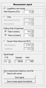
By this I mean is there some way to export the test signal generated by the "Impulse response measurement" function (swept sine, periodic noise etc) as a WAV or FLAC file instead of being played back through the sound card ?
In HOLMImpulse there is a provision to save the measurement signal as a wav file. This is how I managed, fiddling with start/stop, to record FR of my old smart phone.
Attachments
Member
Joined 2003
Having worked with ARTA for some time, there's only a few things that I wish would be changed. I'm not sure if the developer checks this forum, maybe these thoughts would be better suited to a direct email?
LIMP - when completing lead compensation, I short my leads and press the RLC button, which provides values in mOhm and uH, which I then have to move some decimal places to enter this in the lead compensation as Ohms and nH, so it would be great if the units for lead compensation were changed to mOhm and uH.
LIMP - when calculating lossy inductor model, it would be great to see a plot of the modeled impedance to verify that it has a good match to the measured impedance.
LIMP - I fail to understand the need to re-calibrate if the FFT size is changed. The channel difference remains unchanged, but sure enough the results will be out of whack without a re-calibration.
STEPS - The distortion as a % screen is great as it will normalize the response result, so the value is simply % of the fundamental. However, I would prefer to view this data as dB values as well, so -40,-60,-80dB instead of 1%, 0.1%, 0.01%. My thought would be to change the name of this screen to "Normalized Distortion" which a checkbox to change units from dB to %.
ARTA - A plot of the window shape would be great to visualize the different windowing types.
ARTA - I fail to understand why t=0 isn't at bin 300.
ARTA - I would very much prefer if the arrow keys moved the cursor by one bin at a time, rather than simply scrolling the display. For fine cursor placement I always end up zooming in which wouldn't be needed with a simple fine cursor control like using arrow keys.
I think that's all I have for now.
Hi DcibL
I've checked forum but sometimes I expect that other members give their own insights. It helps me to better setup ARTA procedures to user needs.
Let start with your requests and views,
LIMP is offering you to check TSP model - what you need to do after the tsp and inductance estimation is done is to close dialog box and click F3 key. You will get target curve (red one) calculated from estimated parameters..
LIMP calibration is in some cases very critical, especially when you measure capacitance. Even a small error can change angle from 90 to 90.xx value, and the result will be interpreted as inductive. I am trying to fix this for next version.
Plotting of window shape in time domain is not of great help. The fact is that exponential smoothing slightly moves poles and zeros of transfer function, but time function does not reveal that shift. It is better to compare frequency response with different windows.
Reference time zero in ARTA is arbitrary set to sample position 300. There are few reasons for this, the main one is that we works with digitally filtered AD/DA systems that exhibit pre-ringing (which virtually appears before time zero).
Movement of cursor (or marker if exists) can be obtained by clicking keys Shift+cursor.
Ivo
Member
Joined 2003
Hi Ivo, thanks a lot for responding, this is a great help!
The confusion comes to a new user who has set up my mic and expecting time of flight of something like 3ms, but when I place my cursor near the start of the impulse it shows 6ms. The reference impulse is not shown, and I eventually found from another user that it is located at sample 300, and pressing the home key will locate the cursor at sample 300, and I have to measure from sample 300 to the measured impulse to determine time of flight. This was not clear to me when reading through the help file trying to learn the software.
I still think setting t=0 at 300 sample is a good idea, or at least a feature to set t=0 to the cursor location so that it can be arbitrarily set by the user for whatever special case scenario exists.
Perfect! I didn't find this feature documented in the manual, perhaps it could be added to the "view" dropdown menu for easy access.LIMP is offering you to check TSP model - what you need to do after the tsp and inductance estimation is done is to close dialog box and click F3 key. You will get target curve (red one) calculated from estimated parameters..
It's not a big deal, more of a curiosity as I thought the only meaningful result of the calibration is the channel difference.LIMP calibration is in some cases very critical, especially when you measure capacitance. Even a small error can change angle from 90 to 90.xx value, and the result will be interpreted as inductive. I am trying to fix this for next version.
Reference time zero in ARTA is arbitrary set to sample position 300. There are few reasons for this, the main one is that we works with digitally filtered AD/DA systems that exhibit pre-ringing (which virtually appears before time zero).
The confusion comes to a new user who has set up my mic and expecting time of flight of something like 3ms, but when I place my cursor near the start of the impulse it shows 6ms. The reference impulse is not shown, and I eventually found from another user that it is located at sample 300, and pressing the home key will locate the cursor at sample 300, and I have to measure from sample 300 to the measured impulse to determine time of flight. This was not clear to me when reading through the help file trying to learn the software.
I still think setting t=0 at 300 sample is a good idea, or at least a feature to set t=0 to the cursor location so that it can be arbitrarily set by the user for whatever special case scenario exists.
Perfect, thank you!Movement of cursor (or marker if exists) can be obtained by clicking keys Shift+cursor.
Hi Ivo,
Just wondering if it might be possible to add the following:
1.ability to show a legend on the graphs as an option for all of the software
2. the ability to show different colors for mulitple overlay/target curves in LIMP to more closely evaluate the different T/S models
3. Larger FFT option in LIMP?
Thanks,
Jay
Sorry to repeat this but I think it got missed a few pages back.
Member
Joined 2003
Ivo,
I was working with ARTA again today and have a couple simple requests:
- Load FRD or ZMA directly as overlay. Currently in LIMP to load an overlay it requires a saved .lim file, it would be great to be able to load .zma (space separated) or .csv (comma separated) data directly.
While on the LIMP topic, I am curious what information is included in a .lim file that isn't include in a .zma? The .zma is plain text readable by most anything, and the .lim file appears to be binary format that is only readable by LIMP so I am curious what benefit there is to saving the .lim file over the plain text.
Similarly in ARTA - load overlay requires .pir, .sfo or .ovf file, again it would be great to be able to load .frd or .csv plain text files directly as an overlay.
Hey there
I have a strange problem with measurements in art, namely. I have a Focusrite Scarlett 2i2 sound card, when I connect the amplifier and microphone, I start the measurement, I don't have an impulse at point 300. By connecting the loudspeaker to the headphone output, there is also no one. But connecting directly to the output of the sound card, where the signal is weak, the impulse at point 300 appears.
The first thing I noticed is that the problem is the tda2030 amplifier from a single 17V power supply, with a capacitor at the output. So i built on split power supply, but same thing happens, no pulse at point 300.

Soundcard output connect to speaker

Headphones connect to speaker

Amplifier connect to speaker

I have a strange problem with measurements in art, namely. I have a Focusrite Scarlett 2i2 sound card, when I connect the amplifier and microphone, I start the measurement, I don't have an impulse at point 300. By connecting the loudspeaker to the headphone output, there is also no one. But connecting directly to the output of the sound card, where the signal is weak, the impulse at point 300 appears.
The first thing I noticed is that the problem is the tda2030 amplifier from a single 17V power supply, with a capacitor at the output. So i built on split power supply, but same thing happens, no pulse at point 300.
Soundcard output connect to speaker
Headphones connect to speaker
Amplifier connect to speaker
Last edited:
Member
Joined 2003
")