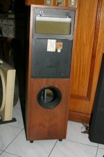
One and only crossover, mounted on bottom "cover" of the LF enclosure (where the spiked feet are mounted). I can post the bottom (trace) view of this board, if anyone is interested...
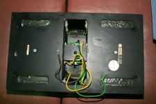
Left side: inputs to the crossover (biwired inputs)
Right side: outputs to LF drivers
Bottom: connections still visible to the multiwire royal cord connecting to the HF/MF enclosure..
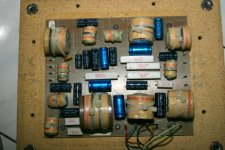
Left side: inputs to the crossover (biwired inputs)
Right side: outputs to LF drivers
Bottom: connections still visible to the multiwire royal cord connecting to the HF/MF enclosure..
Attachments
I have KEF 103/4's (vintage 1992), and need to replace the Uni-Q driver in one of them. Unfortunately, I dissassembled the driver without noting which internal wires went to which posts on the driver. Does anyone happen to know the wiring schema for the Uni-Q driver. I need to know where the yellow, green, brown, and blue wires coming from the crossover connect to the mid-range and tweeter posts on the actual driver. Thanks!
")
Hi Dublin78, I would be interested in a copy of those schematics if, by now, you have scanned them? Actually its a bit late since I just finished renovating my 104s but I originally wanted to see the difference between the bi-wired and the non-bi-wired schematics. Searching on this site you will find my redesigned x-over PCB which I put up earlier today.Hello
I have since managed to get hold of the correct schematics for my 104/2s. They are dated 1990, and seem correct.
There were seemingly different derivatives, even a bi-wire version.
I wanted a schematic, so that I could investigate the possibilities of enhancing the performance with modern components.
I have now decided that the crossovers are extremely complex and carefully balanced, and that any fiddling would do more harm than good.
FYI, my crossovers are one-piece and are located against the back panel of the chassis about half way up. It is not easy to see how they might be removed for service without dismantling a lot of the chassis.
These loudspeakers were built with a "belts and braces" attitude and are incredibly well put together (at the cost of easy access to parts perhaps). All panels are sealed with what looks like a silicon sealer, and the midrange units are completely encapsulated in a rubber-esque resin.
Hey, what price perfection?
https://imgv2-2-f.scribdassets.com/img/document/266612771/original/d3f5736b07/1464741870
Actually, the crossovers are fairly easy to remove. Take off the bottom hatch. Remove bottom bass driver. Then you can get to the crossover. It is secured with six bolts. You might need to remove the top Bass driver to take out the force cancelling bar??? If you need to remove the top bass driver, you do this via the access hatch behind the midrange unit. Your foam donuts will likely be crumbling by now, unless someone has replaced them already. New ferrofluid is another likely job. I have replaced all my caps with a kit from Falcon. Quite an easy job.
Actually, the crossovers are fairly easy to remove. Take off the bottom hatch. Remove bottom bass driver. Then you can get to the crossover. It is secured with six bolts. You might need to remove the top Bass driver to take out the force cancelling bar??? If you need to remove the top bass driver, you do this via the access hatch behind the midrange unit. Your foam donuts will likely be crumbling by now, unless someone has replaced them already. New ferrofluid is another likely job. I have replaced all my caps with a kit from Falcon. Quite an easy job.
Hi dublin78,https://imgv2-2-f.scribdassets.com/img/document/266612771/original/d3f5736b07/1464741870
Actually, the crossovers are fairly easy to remove. Take off the bottom hatch. Remove bottom bass driver. Then you can get to the crossover. It is secured with six bolts. You might need to remove the top Bass driver to take out the force cancelling bar??? If you need to remove the top bass driver, you do this via the access hatch behind the midrange unit. Your foam donuts will likely be crumbling by now, unless someone has replaced them already. New ferrofluid is another likely job. I have replaced all my caps with a kit from Falcon. Quite an easy job.
Thanks - I was hoping that your schematics also had the inductor values in. Also the schematic you mention is the mono-wired version and I was interested in the bi-wired schematic. I reverse engineered my mono-PCB and confirmed that the schematic you linked to is the same as my PCB, then I cut the link between LF drivers and MF drivers. I ended up with this schematic:
If someone around you can give you a LCR meter to measure the coils and a Dayton gadget to trace the impedance curve of the drivers at XO tgen you can abstract the exact caps values in a on line XO simulator like the ML-Audio one. Maybe someone in the swapmet section.
Falcon kit have only 5% precision recap kits left if I remember.
Falcon kit have only 5% precision recap kits left if I remember.
- Home
- Loudspeakers
- Multi-Way
- Kef reference 104/2 circuit diagram