Start of new crossover design for the 18w8545K woofer and the D2509/9900 revelator for the tweeter.
First I did a lot of measurements.
- impedance measurement with speaker workshop.
- Measurement of the frequency response in free air.
I've used a MLS signal with a timeframe of 20msec so I have no reflections in my measurements from the enviroment.
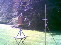
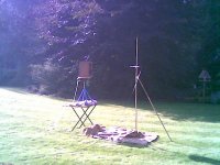
Below you can see pictures of my measurement of my speaker in free air. The microphone is 1 meter in front of the speaker.
The measurements are taken without crossover. So I've measured a separated frequency response for the tweeter and a second for the woofer when the speakers where mounted inside the box.
First I did a lot of measurements.
- impedance measurement with speaker workshop.
- Measurement of the frequency response in free air.
I've used a MLS signal with a timeframe of 20msec so I have no reflections in my measurements from the enviroment.
Below you can see pictures of my measurement of my speaker in free air. The microphone is 1 meter in front of the speaker.
The measurements are taken without crossover. So I've measured a separated frequency response for the tweeter and a second for the woofer when the speakers where mounted inside the box.
Attachments
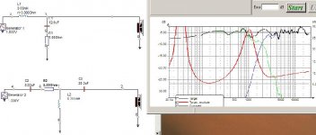
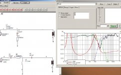
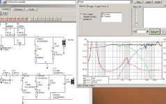
Below you can find the measurements in LspCad for the original filter with reverse polarity of one speaker. As you can see the dip at the crossover frequency is not very deep.
Tomorrow I'm going to post my new crossover design.")
Tomorrow I'm going to post my new crossover design.
Attachments
Congrats, very flat....
My guess your x-over is 4th order or greater...
1. Any details on the x-over?
2. you may like to do some off axis(15 deg, 30 deg, etc) measurements to see how it performs.
one site see below it recommends 3rd or max 4 th order of it to sound good. In fact he prefers 3rd order.
http://home.wanadoo.nl/dezaire/English.htm
see subsection on R & D on testing of x-orders.
I'm still in the design phase of my crossover.
I don't have the components yet to build it. First I want to get as much comments as possible.
When nobody can improve the design more then it is today then I'll buy the components and I'm going to do new measurements. But first I must be sure that I'm on the good way.
When you use the 18w8545K woofer and the D2509/9900 revelator for the tweeter it is not easy to make a good crossover.
The 18W8545K is a brilliant woofer and it will only give its best with a sofisticated crossover.
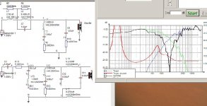
The crossover section for the woofer contains two notch filters to remove the bumps. The crossover section for the tweeter contains also notch filters and a phase correction network. The phase correction network was necessary to get the tweeter perfect in phase with the woofer at the crossover point of 1.9 Khz.
You realy need every component in the crossover.
Salas: I don't know it yet, but I don't think it will sound mechanical because the peak at 2Khz in the frequency response is suppressed by the notch filters.
I don't have the components yet to build it. First I want to get as much comments as possible.
When nobody can improve the design more then it is today then I'll buy the components and I'm going to do new measurements. But first I must be sure that I'm on the good way.
When you use the 18w8545K woofer and the D2509/9900 revelator for the tweeter it is not easy to make a good crossover.
The 18W8545K is a brilliant woofer and it will only give its best with a sofisticated crossover.
The crossover section for the woofer contains two notch filters to remove the bumps. The crossover section for the tweeter contains also notch filters and a phase correction network. The phase correction network was necessary to get the tweeter perfect in phase with the woofer at the crossover point of 1.9 Khz.
You realy need every component in the crossover.
Salas: I don't know it yet, but I don't think it will sound mechanical because the peak at 2Khz in the frequency response is suppressed by the notch filters.
It looks interesting - but only a series C on tweeter at 2khz .... it might look good with higher order slope, but will the tweeter take the strain .... it might give higher distortion, and I would try a paralel inductor (with a series resistor of about the tweeters dc)
And you should try a RC on tweeter... it wont change much on measurements, but you will hear the differense once its playing
Another point ... too many non standard component values, meaning that you will need many paralel/series connections, which can ruin the sound in the end
Otherwise, very serious approach
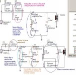
Jonasa said:Below you can find a detailed description about the crossover.
Any suggestions?
In all series RLC combine as much higher L parasitic resistance from cheapest off the shelf inductors and remove the excess from resistors values, so your experimental build can have the lowest cost possible.
Thanks for the suggestions.
Tinitus,you wrote:
Do you mean that there is a risk to overload the tweeter? I was also thinking about this but I wasn't sure. Will it be better that I use a higher order crossover for the tweeter? So that it roll off faster, especially at lower frequenties. And less distortion? Good suggestion.
Why exactly this resistor?
Titinus, I don't understand why. When you look at my graph you can see that the impedance curve is very flat at high frequenties.
Or do you want to suppress the rising peak above 10KHz? For me this bump was no problem because I had the feeling that it sounds more open and gives good imaging when the upper high rise a little.
Tinitus,you wrote:
PHP:
but only a series C on tweeter at 2khz .... it might look good with higher order slope, but will the tweeter take the strain
PHP:
(with a series resistor of about the tweeters dc)
PHP:
And you should try a RC on tweeter... it wont change much on measurements, but you will hear the differense once its playingOr do you want to suppress the rising peak above 10KHz? For me this bump was no problem because I had the feeling that it sounds more open and gives good imaging when the upper high rise a little.
Ups, I am in the fire now
I dont think you should change the slopes much, and I may not be the one to guide you, as you appear far more skilled than I am
paralel coil with a series resistor makes it possible to bend the slopes just slightly and still give some protection to tweeter - and it is my experiense that its good fore phase, when adjustment is
correct
But I am kind of crazy with those resistors and put them in series with all paralel components
It is my experience that RC on tweeter, even on a XT25 with flat impedanse, makes the top more airy and less distorted or less peaked if you like
but I really dont calculate much or measure, I am just listening, whether it is notches or RC they need fine tuning by ear
But lets wait till you have it playing - it will be interesting to hear if it sounds as good as it measures
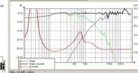
Tomorrow I'll try to make a higher order slope for the tweeter.
It can be that it is enough that I just need to remove the 50 micro farad capacitor from the tweeter network, then it acts like a higher order crossover.
Anyway, when I change this I need to finetune the components from the whole filter again.
I'm going to try at least -30dB at 500Hz for the tweeter.
- Status
- This old topic is closed. If you want to reopen this topic, contact a moderator using the "Report Post" button.
- Home
- Loudspeakers
- Multi-Way
- Closed box design:Scan Speak monitor