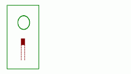
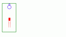
Building a flat box with the Vifa P13WH008. The box volume is 1300 cubic inches, 39L, and the dimensions are 42" high by 8.125" wide by 4" deep. This is really a Mass Loaded Transmission Line.
The selected box tuning is 42 Hz.
The builder wants a really large duct, away from the floor, to prevent vent noise and floor interaction. Toward that end, we decided on a 4" by 2" duct, 13.75" long.
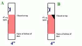
Since the enclosure is only 4" deep, the duct will be a channel bisecting the interior of the box for a certain length. At the top end of the channel is an aperture 4" long by 2" wide. Behind the aperture I anticipate a channel running down the interior for 10 inches or so. The interior opening will be about 6 inches abouve the bottom.
I include a couple of illustrations below.
Two questions.
A) Is there any problem building a duct like this? That is, most ducts use smooth elbows to guide the air smoothly-this one has a sharp right angle from the upward motion of the air to the outside. Shold I kep the sharp right angle in it, like in Fig A, or put in an angle piece to smooth the air flow, like in Fig B.
How long shold the duct be to count as a 13.75" long duct? I am figuring from the center, so it would be 2 inches into the center of the duct from the front of the speaker board, (actually 2.75" if you coant the 0.75" buidling material, but I'm ignoring that right now, plus 11.75" inches from the center of the duct to the open end at the bottom.
In other words, the duct should in fact be 13.75" from the open end to the inside of the top piece. Would that be right?
The duct will be built along an interior wall, (two interior walls, as a matter of fact) wold that afrfect the length requried for tuning to 42 Hz?
Anyway, here are two ilustrations. Sorry for the sloppy drawing. the first is the front view of the speaker as visualized.
Attachments
Why do you hate them? They are nice!  And they work well.
So,.the duct is counted from its center, as you suggested.
I believe it will also work as you have illustrated it (it is not the best duct but you don't have other choices either), but put this angle piece for sure. The duct should be considerably bigger in its surface to work well without this piece.
I've never used one. But Thile recommended one in his paper way back when, so I thought I would see how it where it would lead.pinkmouse said:First thing - I hate square ports!
pinkmouse said:Secondly, and much more importantly, have you simulated the constriction in the box that will be caused by adding all this wood? I can't see that it would work as a MLTL.
I am not sure what you mean. I did compensate for the volume taken up by the port by adding two extra inches to the height. The volume of the duct, including 1/2" building material for the sides, is 165 cu inches. I added 2" onto the height, which gives back around 65 inches, for a net loss of 100cubic inches, which is negligible.
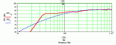
Here is the response chart fo the Vifa in the box which is 40" high instead of 42 inches high-it shold be very close to this.
Attachments
thalis said:Why do you hate them? They are nice!And they work well.
So,.the duct is counted from its center, as you suggested.
I believe it will also work as you have illustrated it (it is not the best duct but you don't have other choices either), but put this angle piece for sure. The duct should be considerably bigger in its surface to work well without this piece.
Thalis:
Thanks for your answer. I always was somewhat suspicious of square or rectangular ports because it would seem to be common sense that corners would be disruptive to smooth airflow. I don't have any proof of this, just guessing.
I am not building this, another member is and I am just assisting him, making suggestions, etc. The simplest way to port this is to simply make a 2" round pipe, 4.75 in long. WinISD gives this design the okay. In fact, WinISD says any round port larger than 1.7 inches in diameter is good, and 2 inches is 40% larger. The straight pipe would vent to the side.
However, the builder seems concerned that the port still might cause port noise, and suggested a port that might also be used as a brace, as well as being larger. So I came up with this design, trying to satisfy both aims.
What I am concerned about is that if you follow the centerline of the port, in order to exit the port it must make a sharp right angle turn. Although having a very large crosssection port might help, if the right angle turn causes possible point noise, I can't see making the cross section large only to hurt the cause with a design that is noisier than a straight pipe of equal cross section.
Which I am concerned this might be, even with that angle piece.
I believe I already answered to this, you won’t have problems with this turn, and he will not hear anything most probably even without this 45 degree angle small wood piece – but you should put it as well. As for the rectangular ports, I have constructed dozens of them and they all worked and measured like a charm. If rectangular shape was measurable disruptive to smooth air flow there would be no building ventilation system with rectangular channels, but they would use pipes instead to save power and energy.
Regards,
Thalis
Regards,
Thalis
Thalis:
Thanks. I will do that, using the angle piece.
I was just curious, though, what you meant when you said,
Thanks. I will do that, using the angle piece.
I was just curious, though, what you meant when you said,
.it is not the best duct but you don't have other choices either
kelticwizard said:I did compensate for the volume taken up by the port by adding two extra inches to the height. The volume of the duct, including 1/2" building material for the sides, is 165 cu inches. I added 2" onto the height, which gives back around 65 inches, for a net loss of 100cubic inches, which is negligible.
What I was thinking is that the port/brace protrudes into the width of the TL, causing it to reduce in sectional area. This is important in TLs, unlike reflex boxes. You can model this in MJK's work by using the TL Sections sheet.
I was initially concerned about that, too. But then I dismissed it because in earlier models using MJK's Sections worksheets for Dalines, I discovered that unless the chamber has a cross section of 3 times greater than the rest of the Line, the Line just sees it as a widening of the Line without that much difference in response outside of the extra volume added-it doesn't really "see" a chamber.
Nevertheless, I shall model this in the Sections worksheet just to make sure. I figure I will model the section containing the duct as being 5.125" wide, while the rest of the enclosure is 8.125" wide. The next section will return to being 8.125" wide. Then I will make the last section equal to the vent dimensions-2" wide, 4" deep, 13.75" long. Although not entirely faithful to the enclosure, where the vent pipe opening will 6" above the bottom-it should give a good approximation. The volume will be a little bit off, since the Sections worksheet will add the volume of the duct to the general overall volume of the enclosure. But since the duct is only 8.3% of the enclosure volume, all it means is that we lose 1 dB at the bottom end-where the chart shows us being 3 dB down, we will actually be 4 dB down. Not much to worry about.
Nevertheless, I shall model this in the Sections worksheet just to make sure. I figure I will model the section containing the duct as being 5.125" wide, while the rest of the enclosure is 8.125" wide. The next section will return to being 8.125" wide. Then I will make the last section equal to the vent dimensions-2" wide, 4" deep, 13.75" long. Although not entirely faithful to the enclosure, where the vent pipe opening will 6" above the bottom-it should give a good approximation. The volume will be a little bit off, since the Sections worksheet will add the volume of the duct to the general overall volume of the enclosure. But since the duct is only 8.3% of the enclosure volume, all it means is that we lose 1 dB at the bottom end-where the chart shows us being 3 dB down, we will actually be 4 dB down. Not much to worry about.
Dear kelticwizard, you are right, I had some reservations. Not regarding the port as such, but rather the matter described above by pinkmouse. Still, the port will see the about same air compliance and will be tuned accordingly. What would perhaps differ, as I imagine it (without modeling the situation), would be a slightly recessed output in the 70-100Hz region relatively to your predicted model.
Regards,
Thalis
Regards,
Thalis
Thalis and Pinkmouse:
Some interesting results.
First, some assumptions. Since the 13.75" long duct has a space 40% it's length beneath it, and a space 160% it's length above it, I am assuming that there is more than ample free flow of air around this duct and that the only effect it will have on the response is the narrowing of the Line. In other words, I am assuming that a 3" wide (including wall thickness) duct down the middle of the enclosure is equivalent to a 3" wide duct on either side, along the wall. I think this assumption is justified, considering all the free flow area above and beneath the duct.
Second, the response curve which was posted earlier here, was made using the Ported worksheet. The center of the port was 3" from the bottom, I believe. The port was a round tube, 2" diameter by 4.75" long. Enclosure tuned to 42 Hz.
The response curves about to follow were made using the Sections worksheet. Both ports modelled tune the enclosure to the same frequency. To use the Sections worksheet, I have to assume that the port is at the very bottom of the enclosure. This might throw some things off. There is a solution. The Ported worksheet has a sections part in itself where you can write in the details. I believe this is the worksheet I should have been using-the sections portion of the Ported worksheet, not the Sections worksheet.
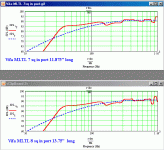
Until I use that Ported worksheet, therefore, these graphs are preliminary. One port has a cross section of 8 sq in-which is our 2" by 4" port. The other, slightly smaller port, has a cross section of 7 sq inches. Ports used in all graphs tune the enclosure to 42 Hz.
What I find is: you can make the port area too large! The 7 sq in port gives smoother response in the midrange than the 8 sq in port. And the smoothest response seems to come from the 2" round port, (3.13 sq in) which I modelled in the Ported worksheet.
Apaprently the MLTL works best when there is a large disconnect between the area of the port and the area of the Line which it is venting.
I'll remodel all this in the Ported worksheet-sections area-later today or tomorrow and get back here to post the results. The port will be modelled as being 6" above the bottom of the enclosure, for that is where the opening will be.
Attachments
I think that Mids get smoother mostly because port self resonances move upwards, beyond them, and at the same time they loose their relative magnitude. With a big port you can have some shifts in the lower mids, in one basic frequency and its multiplies, because there it is where the port air volume will resonate. I like these shifts, nevermind ) I usually go big and put some felt in one of the four sides of my (nowadays) always rectangular ports
BTW, have you modeled these simulations with the same abs.material density?
BTW, have you modeled these simulations with the same abs.material density?
Yes. 0.2 lb/cu ft throughout the enclosure, no stuffing inthe port.thalis said:BTW, have you modeled these simulations with the same abs.material density?
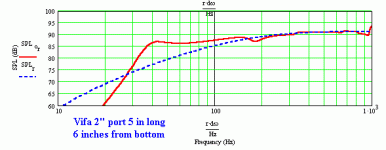
Here is the sim, done in the Ported worksheet, sections area, for a 40" high by 8"(down from 8.125"), wide by 4" deep enclosure. Port: unstuffed, 2" round pipe 5 inches long. Located 6 Inches abouve the bottom of the enclosure.
Quite a difference.
Attachments
- Status
- This old topic is closed. If you want to reopen this topic, contact a moderator using the "Report Post" button.
- Home
- Loudspeakers
- Multi-Way
- Square Duct Questions For Vented Box
