I'm not sure if i'm wording this correctly, please bear with me.
If i use more than one of a given driver, how do i calculate the efficiency of the "array" ?
i've been wanting to build a pair of Karlson cabinets(say what you will about them) and for the HF/mid bit i figured i'd try something a little more unorthodox than a regular old mid + tweeter. in the Karlson's case, it might be easier to achieve an aesthetically pleasing solution this way anyway. plus it makes a method for me to achieve 8 ohm final impedance.
So i was looking around and it seems Tang Band has these 2-inch aluminum drivers that go from 330-20k Hz. it might be debatable whether or not they really achieve that low, but i was going to use them from 800 and up anyway. the woofer i wanted to use was 6 ohms. i figured 4 of these little 2" drivers(8 ohms each) paralleled woudl give me 2 ohms, in series with the 6 ohm woofer equals 8 ohms nominal. i plan to use a Zobel on the woofer, maybe the Tang Bands too.
thing is, the woofer is 95 dB efficient and the Tang Bands are each only 86, or 88 if i get the paper cone version. i don't feel like attentuating the woofer at all because i want high efficiency. if i string together maybe 4 of the TBs per cabinet, what sort of efficiency gain could i achieve for the collective four of them, if at all? how do i calculate or predict that? i guess it would sort of be a mini transmission line because i wanted to vertically stack them on one side of the Karlson box, which would just look like a segment of a line array i once saw built out of these things. not that i have any illusions of achieving the effect of a real line array, more like just a neat looking mid-tweeter stack. i know there is a formula in James Griffin's line array paper, but is that one that really only applies to LA construction?
thanks
If you place two identical low frequency drivers close together (almost touching) they will behave as a single unit with twice the cone area with a 6 db rise in response. Three db from doubling the electrical power and 3 db form the increase in radiation impedance.
The freqency F(0) below which this behavior will give a 3 db increase is given by the equation
f(0) = (c/d)*sqrt")
f(0) = frequency
c = speed of sound in meters
d = center to center distance between the two drivers (in meters)
n = number of drivers used
Ref. Engebretson (1984)
Wolff and Malter (1929)
The freqency F(0) below which this behavior will give a 3 db increase is given by the equation
f(0) = (c/d)*sqrt
f(0) = frequency
c = speed of sound in meters
d = center to center distance between the two drivers (in meters)
n = number of drivers used
Ref. Engebretson (1984)
Wolff and Malter (1929)
Hi Bikehorn,
You need to design, build, test, adjust and re-test a crossover to suits the drive units.
All,
This guy need help
No it won't.. i figured 4 of these little 2" drivers(8 ohms each) paralleled woudl give me 2 ohms, in series with the 6 ohm woofer equals 8 ohms nominal.
You need to design, build, test, adjust and re-test a crossover to suits the drive units.
Why?use a Zobel on the woofer
All,
This guy need help
B4 said:If you place two identical low frequency drivers close together (almost touching) they will behave as a single unit with twice the cone area with a 6 db rise in response. Three db from doubling the electrical power and 3 db form the increase in radiation impedance.
The freqency F(0) below which this behavior will give a 3 db increase is given by the equation
f(0) = (c/d)*sqrt
f(0) = frequency
c = speed of sound in meters
d = center to center distance between the two drivers (in meters)
n = number of drivers used
Ref. Engebretson (1984)
Wolff and Malter (1929)
thanks a lot. at about what frequency point does that stop being effective? based on my calculations, assuming a rougly 2" centre-to-centre spacing and 4 drivers, i got a 3dB boost at 13.8 Khz...if i did my math correctly. i also got the speed of sound in air assuming the temperature was 22 C, so it was 344.82 metres per second.
AndrewT said:Hi Bikehorn,
No it won't.
You need to design, build, test, adjust and re-test a crossover to suits the drive units.
Why?
All,
This guy need help
no doubt i was going to go through various testing to get the crossover right, but i just wanted to be in the general ballpark of 8 ohm final impedance.
As for the zobel, i figured it would probably be good to have a flat-ish impedance curve so that the crossover behaves more predictably. some of the things i've read on crossover design suggest that a zobel is mandatory...i haven't concluded that myself but mind you i'm not an expert either.
i read some more on those 2" Tang Bands and it looks like their HF performance is actually a little wanting - or it was in Darren Kuzma's line array anyway. i think i may just go back to a 3-way with a planar tweeter.
Bikehorn,
My equations and graphs in my Near Field Line Array white paper are correct within the caveats that I mention in my paper. They are correct for line arrays or any other kind of driver array for that matter. You'll get the array gain but you will need to adjust for the impact on sensitivity. The downer in all of this is the caveat of center to center spacing mention by B4 in his reply. I use a rule of thumb of no more than a wavelength spacing between drivers for most of my arrays. With a frame of 2.25 inches the closest c-t-c distance is 2.25" which is 6027 Hz. Hence, your tweeters will have loss of directivity above that frequency and their sensitivities wil not necessarily add. While your ear may miss some of the associated comb lining in the 10-20 kHz octave, I still would not recommend that you use the 4 driver array that you proposed.
To get a feel for how these drivers respond, take a look at the unequalized frequency response data by Darren Kuzma's 32 driver line array with the Tangband W3-880's. Observe the general fall off of the response as frequency increases. Darren used EQ to raise the uppper response as you can see in the equalized plot.
Jim
Ok, here it is, I have a graph but I don't know if I can paste from my computer.
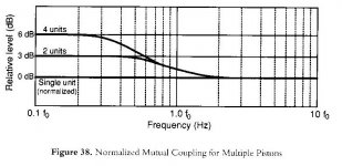
The f(0) you calculated will be the reference point.
For two drivers.
- At .5 * the f(0) will be a full 3db increase
- At 1.1 * f(0) will be no change as compared to a single driver
For 4 drivers.
- At .3 * f(0) you will have a full 6 db increase as compared to a single unit
- At 1.1 * f(0) you will have the same output as a single driver (same as the 2 driver system)
Notice that for the two driver system it says 3 db increase. you would have to also add 3 db to the full frequency response because we doubled the power output going from say 8 ohm to 4 ohm.
f(0) is the point (below) were the mutual coupling becomes effective.
I have modeled the above in Leap and it is almost perfect although Leap also takes diffraction and other things into account. This is a good starting point anyway, final tweaking is obviously necessary. I use 339 m/s for speed, close enough. I get 9,437 Hz using 339 m/s and two drivers, a bit different then yours but I think you will manage.
Good luck
The f(0) you calculated will be the reference point.
For two drivers.
- At .5 * the f(0) will be a full 3db increase
- At 1.1 * f(0) will be no change as compared to a single driver
For 4 drivers.
- At .3 * f(0) you will have a full 6 db increase as compared to a single unit
- At 1.1 * f(0) you will have the same output as a single driver (same as the 2 driver system)
Notice that for the two driver system it says 3 db increase. you would have to also add 3 db to the full frequency response because we doubled the power output going from say 8 ohm to 4 ohm.
f(0) is the point (below) were the mutual coupling becomes effective.
I have modeled the above in Leap and it is almost perfect although Leap also takes diffraction and other things into account. This is a good starting point anyway, final tweaking is obviously necessary. I use 339 m/s for speed, close enough. I get 9,437 Hz using 339 m/s and two drivers, a bit different then yours but I think you will manage.
Yes it is.As for the zobel, i figured it would probably be good to have a flat-ish impedance curve so that the crossover behaves more predictably. some of the things i've read on crossover design suggest that a zobel is mandatory...i haven't concluded that myself but mind you i'm not an expert either.
Good luck
Post #6
bikehorn, with crossovers, 6 + 2 is not equal to 8.
It will be equal to 2 over the crossover frequency and 6 under the crossover frequency.
Exactly. Remember we are talking about impedance here and not DCR. Impedance is frequency dependant. So no matter how you cross the drivers you will not get your 8 ohms. You will have 2ohms for the frequencies that the Tangbands play and you will have 6ohms for your woofer because they are playing different frequencies.
Andrew S- said:
Exactly. Remember we are talking about impedance here and not DCR. Impedance is frequency dependant. So no matter how you cross the drivers you will not get your 8 ohms. You will have 2ohms for the frequencies that the Tangbands play and you will have 6ohms for your woofer because they are playing different frequencies.
ah, thanks for clarifying that. oops, i feel stupid. can you guess this is going to be my first set of DIY speakers?
also, thanks to everyone else who answered/clarified. i'd have replied earlier but i was busy with exams and was not on my computer very much.
since reading this i have radically changed my philosophy...no more tang bands, no 6 ohm woofer, and no pseudo line-array built into the side of a Karlson. the Karlson will have to have some kind of other mid/HF solution.
My equations and graphs in my Near Field Line Array white paper are correct within the caveats that I mention in my paper.
Excuse me for my ignorance, which paper are we talking about, and is it available for download?
Google would have lead you to the answer which is:
http://www.audiodiycentral.com/resource/pdf/nflawp.pdf
Jim
http://www.audiodiycentral.com/resource/pdf/nflawp.pdf
Jim
Wow, this is a recurring experience...
--------------------------------
For low frequencies, driven by a constant voltage, and the drivers are placed close to each other compared to the wavelength:
Efficiency increase of 3 dB, power sensitivity change 3 dB.
If connected in series; input power is reduced by 3 dB: net level change 0 dB, ie voltage sensitivity changes by 0 dB.
If connected in parallel; input power is increased by 3 dB: net level change 6 dB, ie voltage sensitivity changes by 6 dB.
-------------------------------
For high frequencies, driven by a constant voltage, and the drivers are placed far apart compared to the wavelength:
No efficiency increase (0dB), power sensitivity change 0 dB.
If connected in series; input power is reduced by 3 dB: net level change -3 dB, ie voltage sensitivity changes by -3dB.
If connected in parallel; input power is increased by 3 dB: net level change 3 dB, ie voltage sensitivity changes by 3 dB.
Note, however that this is true only for the response averaged over all directions. The on-axis response under anechoic conditions will behave just as if the drivers were mounted close to one another.
------------------------------
That's all well and good up to the point where one overtaxes the amplifier. I usually don't like to go below 6 ohms in any configuration unless I can be assured that there are no drops below 4 ohms.
At any given frequency, running speakers in parallel reduces the impedeance.
1/(1/Q1+1/Q2+1/Q3+....)
So that an amplifier will see three 8 ohm speakers wired in parallel as a 2 2/3 ohm load (a simplification that does not account for inductance - which can make the scenario even worse). It's great to get that extra 6 db. but it reduces your amplifier headroom by exactly 6 db as well. Amplifiers are not infinite current sources. Even though you increased your speakers output at a given voltage, you've doubled the amount of current required to drive them. Your maximum output - and thus your maximum SPL before the amp starts to clip will remain mostly unchanged.
In addition, response curves are partly impedance dependant. By wiring them in parallel, their response peaks may become exaggerated. Milage varies from speaker to speaker, of course. That's probably why someone invented the equalizer.
But it's nice having highly sensitive speakers for when you listen to them at low volume.
I actually prefer the sound of speakers when their wired with an impedance between 6 and 16 ohms. Less gives lots of phat, loose sounding bass and more makes them sound underpowered, IMHO.
But I would certainly not call myself an expert - or even a novice.
In fact, just ignore me...
At any given frequency, running speakers in parallel reduces the impedeance.
1/(1/Q1+1/Q2+1/Q3+....)
So that an amplifier will see three 8 ohm speakers wired in parallel as a 2 2/3 ohm load (a simplification that does not account for inductance - which can make the scenario even worse). It's great to get that extra 6 db. but it reduces your amplifier headroom by exactly 6 db as well. Amplifiers are not infinite current sources. Even though you increased your speakers output at a given voltage, you've doubled the amount of current required to drive them. Your maximum output - and thus your maximum SPL before the amp starts to clip will remain mostly unchanged.
In addition, response curves are partly impedance dependant. By wiring them in parallel, their response peaks may become exaggerated. Milage varies from speaker to speaker, of course. That's probably why someone invented the equalizer
. But it's nice having highly sensitive speakers for when you listen to them at low volume.
I actually prefer the sound of speakers when their wired with an impedance between 6 and 16 ohms. Less gives lots of phat, loose sounding bass and more makes them sound underpowered, IMHO.
But I would certainly not call myself an expert - or even a novice.
In fact, just ignore me...
Yes, true, connecting several speakers in parallel requires more of the amplifer if the full potential of the speaker cluster is to be used. But that is sort of natural.
And it is true regardless of if they are connected in series or parallel.
-In parallel, they require twice the current, the same voltage and twice the power to reach their maximum capability.
-In series, they require twice the voltage, the same current and twice the power to reach their maximum capability.
As AndrewT says, it can be soved by having multiple amplifiers.
And, what is noteworthy is that the doubled power input actually leads to a quadrupled power output. The efficiency has increased by a factor two by the mutual coupling. At least for low frequencies or straight in front of the speaker.
- Status
- This old topic is closed. If you want to reopen this topic, contact a moderator using the "Report Post" button.
- Home
- Loudspeakers
- Multi-Way
- how do multiples of the same driver in a cabinet affect sensitivity?