Hi,
I have made a pair of floorstanding speakers about a year ago, but back then, I had no idea that a crossover had to be designed to match with the drivers, take in account their frequency response, baffle, and so on, so what I had done was to use a "stock" crossover.
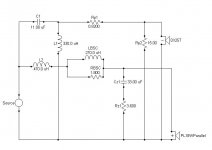
Now that I learned a bit more about loudspeakers, I would like to change the old crossover, and design a new one. I played around with Speaker Workshop's crossover simulator, and after many changes, arrived at the frequency plot attached to this post.
The drivers are two Vifa PL18 (8 ohms) and a Vifa DX25, mounted as an MTM. The big problem is that my baffle is 7.5" wide, and none of the drivers are offset, so the baffle diffraction (simulated with the FRD spreadsheet) is horrible. I have no way yet to measure the frequency response for the drivers mounted in the cabinet, so I used the FR from the D-S-T site, for both the woofer and the tweeter, and then added the simulated baffle diffraction to get the .frd files for the simulation.
I was hoping that some of you with better crossover design knowledge and experience can comment on what I could do to improve the design, assuming that I can't change the cabinet.
All suggestions and comments are greatly appreciated.
Thank you.
Paul
I have made a pair of floorstanding speakers about a year ago, but back then, I had no idea that a crossover had to be designed to match with the drivers, take in account their frequency response, baffle, and so on, so what I had done was to use a "stock" crossover.
Now that I learned a bit more about loudspeakers, I would like to change the old crossover, and design a new one. I played around with Speaker Workshop's crossover simulator, and after many changes, arrived at the frequency plot attached to this post.
The drivers are two Vifa PL18 (8 ohms) and a Vifa DX25, mounted as an MTM. The big problem is that my baffle is 7.5" wide, and none of the drivers are offset, so the baffle diffraction (simulated with the FRD spreadsheet) is horrible. I have no way yet to measure the frequency response for the drivers mounted in the cabinet, so I used the FR from the D-S-T site, for both the woofer and the tweeter, and then added the simulated baffle diffraction to get the .frd files for the simulation.
I was hoping that some of you with better crossover design knowledge and experience can comment on what I could do to improve the design, assuming that I can't change the cabinet.
All suggestions and comments are greatly appreciated.
Thank you.
Paul
Attachments
I simulated the FR for the current crossover, so I can compare the changes, and this is what it gives.
About the speaker measurements, where would I be able to get them measured, i.e. what type of "shops"? The only place near Montreal that I can think of, now that you mentioned this idea, is Solen. I'll send them an email and see if they can measure them.
Paul
About the speaker measurements, where would I be able to get them measured, i.e. what type of "shops"? The only place near Montreal that I can think of, now that you mentioned this idea, is Solen. I'll send them an email and see if they can measure them.
Paul
Attachments
Hi Paul with those narrow baffles I'm geussing that you don't have enough space for a decent chamfer... so you might want to think about using felt on the baffle instead. This was something I was looking at but finding felt thick enough (1/4 inch or so) I was finding difficult. I'm not sure if it needs to be that thick or not, but in my setup the woofers are surface mounted and that's about right to make it flush with the woofers ") .
.
One thing too with BDS is it will give different results depending on what you have the axis distance set at. If you hadn't realised this it is worth working out the distance to your listening position and plugging that in, you might find it is better than you thought it would be (generally I found the longer the distance the less pronounced the simulated diffration effects were).
I also found with BDS that it can give you a false sense of security depending on which mode you use it in. The more advanced modes tend to give (in my experience) a much smoother freq response estimate. I was rather surprised to discover that my 5" morel mw144's actually measured closer to what BDS predicted when using the simple point source calculation, rather than the more complex combined response (ie the diffraction effect modeled as point source seemed to match the actual measured repsonse much better) Ironically the tweeter seems to match better using the combined response calculatio..... I'm thinking this could be because of the shallow cone, and large dome shaped (3" diameter) dust cap, making it behave somewhere in between a cone and a dome, which BDS doesn't allow for.
With regards to doing measurements even a cheap computer microphone (whilst not particularly accurate) when teamed up with speakerworkshop can show you trends..... things such as whether you have your drivers connected with the right polarity should show up as should any large abhorations in the freq response. just don't trust it too much below maybe 500Hz and above say 5Khz.
One final aspect that I'm not sure whether BDS properly allows for, is that in an MTM the top and bottom of the baffle will be less important in the simulation of diffraction than if the tweeter is mounted by itself on a similar baffle, due to the focussing nature of the M's on either side of the tweeter. I found by varying the disatance to the top and bottom of the cabinet (rather than having the tweeter smack bang in the middle) it effected the modelling quite a bit, however I don't beleive in an MTM it should make that much difference.... perhaps when you set the speakers as 1, 2 and 4, or 2, 3 and 5 (and choose wMTMw, it does allow for the MTM component, but I didn't seem to get any changes in the results when experimenting in this way with BDS.
Tony.
edit: BTW if you try the cheap computer mic, you can compare the results to your simulated result for the existing crossover it's going to depend on the accuracy of the D-S-T measurements compared to your drivers, and the BDS sim, but it might give you an idea of whether your mic is working ok if it looks similar, then I'd say you are on the right track with the other sim, which looks much better IMO than the model for your stock crossover!
.One thing too with BDS is it will give different results depending on what you have the axis distance set at. If you hadn't realised this it is worth working out the distance to your listening position and plugging that in, you might find it is better than you thought it would be (generally I found the longer the distance the less pronounced the simulated diffration effects were).
I also found with BDS that it can give you a false sense of security depending on which mode you use it in. The more advanced modes tend to give (in my experience) a much smoother freq response estimate. I was rather surprised to discover that my 5" morel mw144's actually measured closer to what BDS predicted when using the simple point source calculation, rather than the more complex combined response (ie the diffraction effect modeled as point source seemed to match the actual measured repsonse much better) Ironically the tweeter seems to match better using the combined response calculatio..... I'm thinking this could be because of the shallow cone, and large dome shaped (3" diameter) dust cap, making it behave somewhere in between a cone and a dome, which BDS doesn't allow for.
With regards to doing measurements even a cheap computer microphone (whilst not particularly accurate) when teamed up with speakerworkshop can show you trends..... things such as whether you have your drivers connected with the right polarity should show up
as should any large abhorations in the freq response. just don't trust it too much below maybe 500Hz and above say 5Khz.One final aspect that I'm not sure whether BDS properly allows for, is that in an MTM the top and bottom of the baffle will be less important in the simulation of diffraction than if the tweeter is mounted by itself on a similar baffle, due to the focussing nature of the M's on either side of the tweeter. I found by varying the disatance to the top and bottom of the cabinet (rather than having the tweeter smack bang in the middle) it effected the modelling quite a bit, however I don't beleive in an MTM it should make that much difference.... perhaps when you set the speakers as 1, 2 and 4, or 2, 3 and 5 (and choose wMTMw, it does allow for the MTM component, but I didn't seem to get any changes in the results when experimenting in this way with BDS.
Tony.
edit: BTW if you try the cheap computer mic, you can compare the results to your simulated result for the existing crossover
it's going to depend on the accuracy of the D-S-T measurements compared to your drivers, and the BDS sim, but it might give you an idea of whether your mic is working ok if it looks similar, then I'd say you are on the right track with the other sim, which looks much better IMO than the model for your stock crossover!oh one other thing, did you also get the impedance plots from D-S-T and use them in your simulations (wondering how you got the zobel component values for the woofer, they are surprisingly close to what I came up with for my MTM )
edit: just realised you probably measured it doh.... it is acoustic measurements you can't do at the moment right?
Tony.
) edit: just realised you probably measured it doh.... it is acoustic measurements you can't do at the moment right?
Tony.
Hi Tony, thank you for your post.
In the sims, I also used the D-S-T impedance curves; I decided to try to get all the data from the same source, but don't know if it really matters.
Your guess was right, I don't have much space right now for wider baffled speakers, and so I'm stuck with them narrow.
From what you wrote, it seems that there are a lot of possible flaws with using the BSD for a more or less accurate simulation, and that real measurements are a necessity for a good crossover. So I'm getting tempted to try some measurements, using a WM61 mic, but the problem will be the actual setup, since it's really cold outside, and I don't really know how big a room must be for good measurements.
Would a WM61 and a simple DIY mic pre do the trick for passable measurements?
Thank you.
Paul
That's pretty much what I'm using though I've got a WM60AY mic.... for higher frequency measurements I don't think a huge room is necessary, A high ceiling will help (10' or more) and big enough to get at least 1.5 X the mic speaker distance to any walls would be nice
make sure you read the SW phase section on Claudio's site carefully though.
I guess one of the problems with BDS is that because the driver has it's own deviations from flat response, it is difficult (without measuring the driver on an infinite baffle first) to make a really good correlation between the BDS results and the actual measured response on the final baffle. I can see a definite trend with mine, but the magnitude is of the deviations is actually worse than predicted by BDS,
I've just bought Joe d'appolitos testing loudspeakers, and I'm hoping to redo my measurements before too long, I think there have been a few mistakes I have been making... might get some better results soon.
BTW doing actual impedance measurements with SW is pretty easy, and much less error prone than accoustic ones.... probably worth doing as the impedance curve IMO will probably effect your crossover design (making it deviate from what you expect) more than any other parameter, so if you at least have that accurate you will have a flying start
Tony.
though I've got a WM60AY mic.... for higher frequency measurements I don't think a huge room is necessary, A high ceiling will help (10' or more) and big enough to get at least 1.5 X the mic speaker distance to any walls would be nice make sure you read the SW phase section on Claudio's site carefully though.
I guess one of the problems with BDS is that because the driver has it's own deviations from flat response, it is difficult (without measuring the driver on an infinite baffle first) to make a really good correlation between the BDS results and the actual measured response on the final baffle. I can see a definite trend with mine, but the magnitude is of the deviations is actually worse than predicted by BDS,
I've just bought Joe d'appolitos testing loudspeakers, and I'm hoping to redo my measurements before too long, I think there have been a few mistakes I have been making... might get some better results soon.
BTW doing actual impedance measurements with SW is pretty easy, and much less error prone than accoustic ones.... probably worth doing as the impedance curve IMO will probably effect your crossover design (making it deviate from what you expect) more than any other parameter, so if you at least have that accurate you will have a flying start
Tony.
Cal Weldon said:It would sure be neat if you could find a way of getting an FR graph before and after. I would really like to see the results, and hear your impressions of the difference of course. No place in grand old Montreal you could take them to get tested?
St.Hubert close enough?
call me I have someone who did miracles with my speakers
514.573.8192
Hi newfinish,
Thanks for the info, I sent you an email about it, and also read your reply in your thread.
@ Tony,
I read Claudio's tutorial for SW a few times, and I'll start making the cables for the calibration and impedance measurement as soon as I'm done with my harder exams. Is it possible to skip the whole soundcard testing, and use the appropriate values that Claudio gives for the soundcard, and go straight to the calibration?
Thanks.
Paul
Hi Paul,
If you have one of the sound cards is Claudio's database then you can probably use the levels recommended. The latency is something though that may be affected by the combination of sc and computer so you probably should do the tests to work that out to be on the safe side.
This (the latency) was an area that I had read before but didn't fully understand, and didn't worry about, I didn't realise that the measurement.in.l and measurement.in.r (under the system folder) were changing every time I did a measurement, because the time and date stamp on them never changed. I also didn't realise that changes of as little as 0.2 ms could make a difference... I'm one of the lucky ones in that the latency difference for my card is allways the same for both channels, so I can just check the reference channel and make sure it is the same whenever I do a measurement (and redo it if it isn't) and know that my phase measurements will be correct.
All I did to check channel to channel latency difference was set up an mls signal (with loop cable attached), and kept hitting record with measurement.in.l (under system folder) on screen, with the measurement.in.r dataset added. Both waveforms always lined up (with the occasional very slight difference in amplitude on a few peaks). I also could see from this what the most freqent latency value was, so I knew which one I should use for my measurements.... one particular latency came up about 60% of the time.
Tony.
Paul wrote:
Is it possible to skip the whole soundcard testing, and use the appropriate values that Claudio gives for the soundcard, and go straight to the calibration?
Hi,
maybe you are refering to the sound card impedance calibration (impedance and capacitance values): in this case the answer is yes, in my opinion; for the rest follow Tony advises.
Regards,
Claudio
- Status
- This old topic is closed. If you want to reopen this topic, contact a moderator using the "Report Post" button.
- Home
- Loudspeakers
- Multi-Way
- Suggestions on my crossover design?