Tony, if you haven't seen it read http://www.diyaudio.com/forums/multi-way/156119-building-stainless-steel-timber.html . I achieved time alignment differently, this was prior to the DMS37.
Terry
Terry
Hi Terry, I'll give it a go, but that is a very high crossover freq isn't it? About 7K?? Not that I can trust my original measurements (as looking back I don't think any two are the same) but one thing that was common in all of them was the MW-144's seemed to have a peak at 5K and then roll off steeply from there.
Actually I've just had a look at some of those "measurements" and from the graph it would appear that the rolloff was something greater than 24db / octave so I think it is highly suspect")
Cheers,
Tony.
Actually I've just had a look at some of those "measurements" and from the graph it would appear that the rolloff was something greater than 24db / octave so I think it is highly suspect
Cheers,
Tony.
It was an educated guess I had a look at the DMS-37's impedance curve to get a rough idea of the impedance around the freq and then used a first order calculator... (also thought that I'd used a 6.8 to cross at around 3K) when testing the prototype...
My memory was out by a factor of ten apparently! the polyprops are .15 .22 .33 .47 and .68uF.... the rest are bipolar electros... I think I bought the polyprops for fine tuning purposes, and the electros for crude experimenting...
I've been looking at more measurements (even though they are suspect), and I can see now how this can work... the DMS-37 has some peaks between 3 and 6K where as the MW-144 has some dips.... quite possible they will even each other out
Tony.
I had a look at the DMS-37's impedance curve to get a rough idea of the impedance around the freq and then used a first order calculator... (also thought that I'd used a 6.8 to cross at around 3K) when testing the prototype... My memory was out by a factor of ten apparently! the polyprops are .15 .22 .33 .47 and .68uF.... the rest are bipolar electros... I think I bought the polyprops for fine tuning purposes, and the electros for crude experimenting...
I've been looking at more measurements (even though they are suspect), and I can see now how this can work... the DMS-37 has some peaks between 3 and 6K where as the MW-144 has some dips.... quite possible they will even each other out
Tony.
look what I found!!
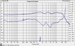
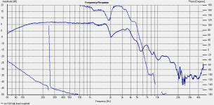
Apparently I have done measurements with the MW-144 running full range with just a 3.3uF cap on the tweeter
I thought that this looked pretty rough at the time but a bit of changing of the graph axis makes it look a little more respectable, and if I took 72db as being the middle it would be almost +- 3db which I guess isn't that bad, especially considering the inadequacy of the measurement setup...
anyway it makes me keener to do some proper measurements. On top of the bad test environment, the boxes weren't sealed, and the baffle will be getting the chamfer so still some room for improvement (other than in the measurement technique).
Tony.
Attachments
Looking at that, I would guess you didn't have much in the way of sound deadening material in the box at the time. If you look at mine it is +/- 2. You should get an improvement.
I'll wait until you have the drivers mounted and then we can play with the other viarables. It's all fun and you may learn a lot.
Best linning I have used is made by tontine, if they still make it, it was called TBL 25/40. 25 is the thickness and 40 was the weight. It comes in sheets 2.4*1.2.
Terry
I'll wait until you have the drivers mounted and then we can play with the other viarables. It's all fun and you may learn a lot.
Best linning I have used is made by tontine, if they still make it, it was called TBL 25/40. 25 is the thickness and 40 was the weight. It comes in sheets 2.4*1.2.
Terry
That's probably right Terry, I didn't make a note so not sure, but I suspect it might have had some of the soundsorber on the back but none on the top/bottom/sides and definitely no fill. I know the best looking measurement I got was with some stuffing but I also have a recolection I didn't care for the sound, but that was with the original prototype box not the final.
Looking at the measurements they are all over the place. Some show the tweeter with a big peak between 4 and 5K and others none, but rolling off from 10k (whilst others are flat out to about 15-17K) I really think I had something very screwy going on with the measurements, no consistency what so ever.
Tony.
Hi Terry,
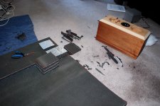
Just found some more measurements I'd done, they were saved under a different directory, I knew I had better examples that what I could find
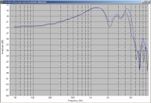
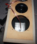
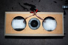
These were nearfield measurements of the drivers in box with damping material only on the rear wall of the enclosure.
The tests were done with no damping, Clarke rubber egg crate foam, and SoundSorber Barrier (I think they now call it something else) on the rear of the enclosure.
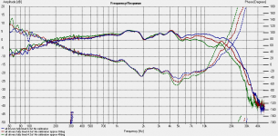
As you can see from the graphs the soundsorber is quite effective at getting rid of the first and partially the second peak... I want to do more tests with back top and bottom lined, will do that sometime in the not too distant future, and that may get rid of some of the other irregularities..
The big notch at 2K I'm sure is measurement related (probably diffraction/interference effects as it is way past the useable range of nearfield measurements) , as I found a nearfield measurement of my 10" vifa's which had an almost identical notch.
edit: I also found a nearfield measurement of one of my Vifa M26WR-09-08's in free air just to show the similarity at 2K and above...
Tony.
Just found some more measurements I'd done, they were saved under a different directory, I knew I had better examples that what I could find
These were nearfield measurements of the drivers in box with damping material only on the rear wall of the enclosure.
The tests were done with no damping, Clarke rubber egg crate foam, and SoundSorber Barrier (I think they now call it something else) on the rear of the enclosure.
As you can see from the graphs the soundsorber is quite effective at getting rid of the first and partially the second peak... I want to do more tests with back top and bottom lined, will do that sometime in the not too distant future, and that may get rid of some of the other irregularities..
The big notch at 2K I'm sure is measurement related (probably diffraction/interference effects as it is way past the useable range of nearfield measurements) , as I found a nearfield measurement of my 10" vifa's which had an almost identical notch.
edit: I also found a nearfield measurement of one of my Vifa M26WR-09-08's in free air
just to show the similarity at 2K and above...Tony.
Attachments
Last edited:
Hi Terry,
Internal dimentions are:
151mm W X 173mmH X 211mm deep. I had a thing for prime numbers when I was designing it Was good as it comes out at 5.5L which is about right for allowing for the 10% or so advised to go over for bracing and driver displacement etc
So it seems likely the 2K dropout is related to a top to bottom reflection. Putting the damping material there should help alleviate it... Unless of course it is a problem with my mike, since the other graph is my 10" in free space and has the same drop!
Yes I was quite happy with the sound absorber, but I haven't yet determined it's properties with regards to effect on box volume! Will do some impedance measurements with and without and see how it alters things.
Tony.
Internal dimentions are:
151mm W X 173mmH X 211mm deep. I had a thing for prime numbers when I was designing it
Was good as it comes out at 5.5L which is about right for allowing for the 10% or so advised to go over for bracing and driver displacement etc So it seems likely the 2K dropout is related to a top to bottom reflection. Putting the damping material there should help alleviate it... Unless of course it is a problem with my mike, since the other graph is my 10" in free space and has the same drop!
Yes I was quite happy with the sound absorber, but I haven't yet determined it's properties with regards to effect on box volume! Will do some impedance measurements with and without and see how it alters things.
Tony.
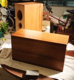
Well today marks another milestone! I've done the burnishing. Mya (my 2 YO) is in China at the moment so I finally had some time when there was no issue leaving something toxic sitting on the balcony for a number of hours. The organ oil hard burnishing oil I used has a warning about it being quite toxic if injested so I was a bit paranoid about leaving speakers with it all over them in reach of my daughter.
Anyway I think I'm going to have very sore arms tomorrow, but first impressions are that the hard work was worth it. I'll know better in a couple of days once it has properly dried and I do the final buff.
Anyway here are a couple of pictures of the finished product... Now all that is left to do is to take some measurements, chamfer the baffles (take some more measurements so I know if the chamfers actually do anything), work out what to finish the front baffles with, make some grills, and do the crossovers (the single 3.3uF cap is looking very appealing).
Other than that I need to make my active crossover for the woofer / MTM cross, which will be at 200Hz. I've designed it, I've ordered quite a few of the parts, I just need to work out the layout.
So though it has been quite a while since I last posted I have been making progress, though until today it was on other areas of the project
Tony.
I've done the burnishing. Mya (my 2 YO) is in China at the moment so I finally had some time when there was no issue leaving something toxic sitting on the balcony for a number of hours. The organ oil hard burnishing oil I used has a warning about it being quite toxic if injested so I was a bit paranoid about leaving speakers with it all over them in reach of my daughter. Anyway I think I'm going to have very sore arms tomorrow, but first impressions are that the hard work was worth it. I'll know better in a couple of days once it has properly dried and I do the final buff.
Anyway here are a couple of pictures of the finished product... Now all that is left to do is to take some measurements, chamfer the baffles (take some more measurements so I know if the chamfers actually do anything), work out what to finish the front baffles with, make some grills, and do the crossovers (the single 3.3uF cap is looking very appealing).
Other than that I need to make my active crossover for the woofer / MTM cross, which will be at 200Hz. I've designed it, I've ordered quite a few of the parts, I just need to work out the layout.
So though it has been quite a while since I last posted I have been making progress, though until today it was on other areas of the project
Tony.
Attachments
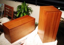
Thanks Terry I chose the blackwood because I already had a blackwood dining table and chairs (ironically now in storage). I didn't know whether I'd be able to match the colour but the tung oil seems to have done the trick nicely Ditto on the comments I made to David, I regard you as being the master of speaker finishing
I'm still debating what to do with the front baffles. Originally I was just thinking I'd do a satin black (might be a bit of a problem now with some oil bleed into the mdf). I could just oil them (at the risk of swelling the MDF) or perhaps some estapol. I really liked your leather baffles in one of your threads, but I think that might be a little beyond me, as I don't know how I'd deal with the baffle edges.
Actually I remember now... I was going to get some 5mm felt and glue it on (after dying it black) will be ugly but provided I make some nice grills it won't be seen. The grills are going to be the next engineering challenge, as I wasn't planning on doing anything conventional
Tony.
I chose the blackwood because I already had a blackwood dining table and chairs (ironically now in storage). I didn't know whether I'd be able to match the colour but the tung oil seems to have done the trick nicely Ditto on the comments I made to David, I regard you as being the master of speaker finishing I'm still debating what to do with the front baffles. Originally I was just thinking I'd do a satin black (might be a bit of a problem now with some oil bleed into the mdf). I could just oil them (at the risk of swelling the MDF) or perhaps some estapol. I really liked your leather baffles in one of your threads, but I think that might be a little beyond me, as I don't know how I'd deal with the baffle edges.
Actually I remember now... I was going to get some 5mm felt and glue it on (after dying it black) will be ugly but provided I make some nice grills it won't be seen. The grills are going to be the next engineering challenge, as I wasn't planning on doing anything conventional
Tony.
Well I only have one running, so mono, but it is currently playing Ella and Louis (The Verve rematered one) and wow does it sound nice
I didn't have any 3.3uf film caps Terry so I hooked it up with a 3.3uf bipolar electro and it sounded quite awfull... I tried a 6.8uf film cap (also awful but in a different way). I then tried a 2.2uf film and thought it was quite good (was listening to David Attenborough) voices sounded very natural. I had another 2.2uf film so paralleled them up, sounded different but not as good. so went back to the single 2.2uf Polyprop cap. I would have thought it was way to high a crossover point but at least on this CD it sounds great.
5 minutes of Jenifer Warns with the 4.4uf and I wanted to turn it off so I now know what you mean about if I cross lower I won't be able to run the 144's full range.
If Jaycar is open tomorrow I might drop in and get some 3.3uf Polyprops. I've ordered some Axon 3.3's but some of the other parts are on backorder so going to have to wait for those.
Cheers,
Tony.
PS. I better get to making up the second set of fly leads for the second speaker!!
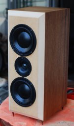
Progress update Now have the other speaker running, though I didn't have another 2.2uf Polypropylene cap only a 2.2uF polyester one, so that is currently serving as the crossover on the second one.
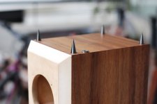
I decided to actually "finish" it before putting the speakers in, so today was spent chamfering the baffle and putting on the legs which took a lot longer than I would have guessed. This wasn't without it's mishaps, the routing went mostly smoothly but I have a wiggle in the nice even chamfer unfortunately at the top on one side. Oh well it isn't that bad.
Had a slight mishap when I drilled the first hole for the legs too. the drill split off the veneer when it caught. Only drilled a small pilot hole followed by the actual size needed for the inserts that the legs screw into. Taped the next three and also used a router bit to take it out at the top before drilling the rest, that mostly worked better.
Anyway I'm not going to comment on sound yet as the setup is not complete. One is chamfered with legs and one not, I don't have the active crossover built yet so they are definitely bass shy (though what bass they have is tight), and I haven't bought the 3.3uF caps yet because at around $7 each for no-names, when I'm getting my Axons for $1.53 each, I thought I'd just wait...
Also until I build my B1 based crossover I can't use my DV18 as my amp has a problem with it which causes distortion, which I'm hoping will be cured by the B1, The HT PC I'm dubious about the quality of as far as being a CD player is concerned.
Having said all that It's not that it sounds bad, it sounds good, but some things just don't sound quite right. But as I said it is not complete, no measurements have been done yet and with only a 2.2uf Cap on the tweeter it is crossed a little high...
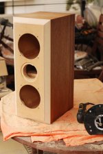
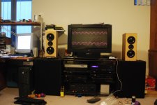
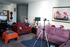
Here are the latest pics, from left to right, just after finishing routing, feet installed (you can see where the veneer split off and I super glued it back on), speakers installed, wired up ready to go, in place.
I will do the other one after I've taken some measurements with and without chamfer.
The colour looks different in daylight to what it did in the last pics (which were taken under halogen light). It is interesting it depends completely on the angle you look at them from they vary significantly as you move around.
Tony.
Now have the other speaker running, though I didn't have another 2.2uf Polypropylene cap only a 2.2uF polyester one, so that is currently serving as the crossover on the second one. I decided to actually "finish" it before putting the speakers in, so today was spent chamfering the baffle and putting on the legs which took a lot longer than I would have guessed. This wasn't without it's mishaps, the routing went mostly smoothly but I have a wiggle in the nice even chamfer unfortunately at the top on one side. Oh well it isn't that bad.
Had a slight mishap when I drilled the first hole for the legs too. the drill split off the veneer when it caught. Only drilled a small pilot hole followed by the actual size needed for the inserts that the legs screw into. Taped the next three and also used a router bit to take it out at the top before drilling the rest, that mostly worked better.
Anyway I'm not going to comment on sound yet as the setup is not complete. One is chamfered with legs and one not, I don't have the active crossover built yet so they are definitely bass shy (though what bass they have is tight), and I haven't bought the 3.3uF caps yet because at around $7 each for no-names, when I'm getting my Axons for $1.53 each, I thought I'd just wait...
Also until I build my B1 based crossover I can't use my DV18 as my amp has a problem with it which causes distortion, which I'm hoping will be cured by the B1, The HT PC I'm dubious about the quality of as far as being a CD player is concerned.
Having said all that It's not that it sounds bad, it sounds good, but some things just don't sound quite right. But as I said it is not complete, no measurements have been done yet and with only a 2.2uf Cap on the tweeter it is crossed a little high...
Here are the latest pics, from left to right, just after finishing routing, feet installed (you can see where the veneer split off and I super glued it back on), speakers installed, wired up ready to go, in place.
I will do the other one after I've taken some measurements with and without chamfer.
The colour looks different in daylight to what it did in the last pics (which were taken under halogen light). It is interesting it depends completely on the angle you look at them from they vary significantly as you move around.
Tony.
Attachments

Last edited:
Well I did some quick and dirty measurements yesterday. Still using speakerworkshop (because I (think I) know how to use it). I didn't get out my testing loudspeakers book. I just wanted to do some dodgy measurements to see if there was any percievable difference between the chamfered and non chamfered boxes.
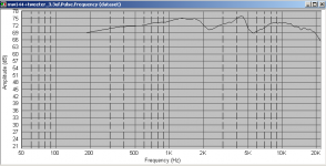
I'm only going to post the DMS37 result as it looks reasonable. The MW144 measurements still look awfull!!
For the tweeter it seems that the chamfer really does have a positive effect, if my dodgy measurements can be at all trusted.
I basically had the speaker sitting in the middle of the room, only slightly elevated above the floor. The mic was at a distance of 0.5M (about the same height the tweeter was off the floor). As I said quick and dirty and not a proper measurement, but it does show differences. the box without the chamfer shows significantly more variation in the response. As a sanity check I swapped the tweeter to make sure the difference wasn't between the units and there was only a very minor difference (probably due to me moving the box slightly from its original position). That is a factor that could be in play between the measurements of the two boxes but I'll do some better measurements outside on the balcony once there is some still weather and no road noise! (might be waiting a while)
Actually I will post the MW144 graphs despite their hideousness... Also the graph of the complete system I did in holm impusle with the not correct 2.2uF cap on the tweeter... certainly some interference happening by the looks of it.
Oh and the blue traces are without chamfer. Strangely for the MW144's the chamfer seems to have made it worse! Though I suspect that the measurement distance is too small and I might be getting interference effects. A 1M or more measurement might show a quite different result. I probably should have taken a measurement with only the top speaker running.. Measurement was taken at 0.5M centered on the tweeter.
Note I didn't read anything about how to use holm impulse before doing that measurement so take it with a big grain of salt. But it does show that there is a problem at around 2.5K and again at about 5.5K... also due to the gating I think it has padded out the low frequencies, there is no way these speakers are flat out to 20Hz
Tony.
I'm only going to post the DMS37 result as it looks reasonable. The MW144 measurements still look awfull!!
For the tweeter it seems that the chamfer really does have a positive effect, if my dodgy measurements can be at all trusted.
I basically had the speaker sitting in the middle of the room, only slightly elevated above the floor. The mic was at a distance of 0.5M (about the same height the tweeter was off the floor). As I said quick and dirty and not a proper measurement, but it does show differences. the box without the chamfer shows significantly more variation in the response. As a sanity check I swapped the tweeter to make sure the difference wasn't between the units and there was only a very minor difference (probably due to me moving the box slightly from its original position). That is a factor that could be in play between the measurements of the two boxes but I'll do some better measurements outside on the balcony once there is some still weather and no road noise! (might be waiting a while
) Actually I will post the MW144 graphs despite their hideousness... Also the graph of the complete system I did in holm impusle with the not correct 2.2uF cap on the tweeter... certainly some interference happening by the looks of it.
Oh and the blue traces are without chamfer. Strangely for the MW144's the chamfer seems to have made it worse! Though I suspect that the measurement distance is too small and I might be getting interference effects. A 1M or more measurement might show a quite different result. I probably should have taken a measurement with only the top speaker running.. Measurement was taken at 0.5M centered on the tweeter.
Note I didn't read anything about how to use holm impulse before doing that measurement so take it with a big grain of salt. But it does show that there is a problem at around 2.5K and again at about 5.5K... also due to the gating I think it has padded out the low frequencies, there is no way these speakers are flat out to 20Hz
Tony.
Attachments
OK well I've given up on taking measurements with speaker workshop and have decided to try holm impulse. Whilst I didn't drag everything outside I did clear the living room a bit and set up with a stand and took some measurements at 1M (about 1.4M off the floor and 1.1M from the ceiling)
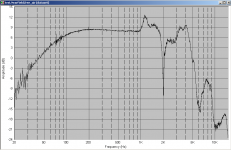
Doesn't matter what I do the dip at 2Khz is still prominent. The DMS 37 measurements don't show it, so it isn't the baffle or the measurement setup. I added some sound absorber on one side of the cab of one of the woofers and this smoothed out a step from 800 to 1000Hz (shows on the nearfield), but it had no effect on the 2K dip. I also went to woolies and bought a tontine pillow to get some stuffing.... put some in and it and it smoothed things out a little more between 400 and 700Hz. Strangely it seemed to make the dip around 5.5K much worse, but I suspect this is actually a diffraction effect which was amplified by a slightly different mic position after taking the speaker down to put the stuffing in.
It's not an interference problem between the two units because I get an identical result (only lower db) if I measure just one).
It also isn't the tweeter as I covered it with some foam and still no change.
There are only two things left that I think it can be.
1. the driver cutouts are still too tight. I will try taking it out another 2mm or perhaps 3mm and see if anything changes.
2. This is something inherent with the drivers, if it is I suspect it is a basket reflection which is coming back out of phase. This I think is the more likely explanation, as I do recall that I tried measuring these in free air and still saw the same dip at around 2K.
Anyway If I can't fix it I'll live with it, because they don't sound bad to me
latest pics attached.
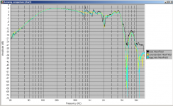
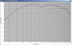
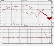
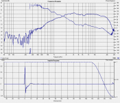
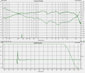
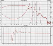
1st is 1M gated measurement of just the MW144's 2nd is 1M DMS37 gated measurement. 3rd is 1M gated with all drivers running and 3.3uF Axon cap on the tweeter. 4th is a single MW144 with stuffing added Nearfield measurement, as can be seen it is very good from 200Hz through to about 1.6K after which it falls off a cliff... Finally a picture of the measurement setup... not great but better than my previous ones!!!
Tony.
Doesn't matter what I do the dip at 2Khz is still prominent. The DMS 37 measurements don't show it, so it isn't the baffle or the measurement setup. I added some sound absorber on one side of the cab of one of the woofers and this smoothed out a step from 800 to 1000Hz (shows on the nearfield), but it had no effect on the 2K dip. I also went to woolies and bought a tontine pillow to get some stuffing.... put some in and it and it smoothed things out a little more between 400 and 700Hz. Strangely it seemed to make the dip around 5.5K much worse, but I suspect this is actually a diffraction effect which was amplified by a slightly different mic position after taking the speaker down to put the stuffing in.
It's not an interference problem between the two units because I get an identical result (only lower db) if I measure just one).
It also isn't the tweeter as I covered it with some foam and still no change.
There are only two things left that I think it can be.
1. the driver cutouts are still too tight. I will try taking it out another 2mm or perhaps 3mm and see if anything changes.
2. This is something inherent with the drivers, if it is I suspect it is a basket reflection which is coming back out of phase. This I think is the more likely explanation, as I do recall that I tried measuring these in free air and still saw the same dip at around 2K.
Anyway If I can't fix it I'll live with it, because they don't sound bad to me
latest pics attached.
1st is 1M gated measurement of just the MW144's 2nd is 1M DMS37 gated measurement. 3rd is 1M gated with all drivers running and 3.3uF Axon cap on the tweeter. 4th is a single MW144 with stuffing added Nearfield measurement, as can be seen it is very good from 200Hz through to about 1.6K after which it falls off a cliff... Finally a picture of the measurement setup... not great but better than my previous ones!!!
Tony.
Attachments
Well I've been at it again I'm supposed to be finalising the BOM for my Synergy Active Crossover which will be used to cross to my 10" vifa woofers, but I couldn't resist doing more measurements.
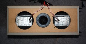
I decided to take a no holds barred approach to lining the cabinet. I was concerned that the thickness of the sound deadening material would be detrimental to the volume of the cabinet or possibly even cause interference, but I was wrong! I lined all of the walls (some not quite up to the woofer, and put a taper on the foam away from the woofer so that it wasn't presented with a straight edge but rather something closer to 45deg), and then for good measure filled up the remaining hole with some polyester fibres from a pillow I bought at woolies
I've only done one of the boxes so far, the nearfield measurement reveals a slightly smoother response and I think that the 1M measurement is also slightly better. Subjectively I think it sounds a little less honky or less like there has been echo added. the other thing that comes to mind is slightly less constrained, very hard to put into words.
Oh and I took some off axis measurements as well, didn't have a protractor handy so the 15 and 45 degrees are best guesses.... surprisingly good out to about 5K at 45degrees off axis!!! still very good at 60deg!
Oh and the other thing I did was change to a 4.3 uF cap, this results in a slightly smoother response as well. At first I didn't like the sound but after a little while got used to the difference
And finally I worked out where the 5.5K dip is coming from. It corresponds exactly to the width of the baffle to the start of the chamfer. so I guess that is a good reason for chamfering the baffle, it pushes up the frequency that the baffle diffraction happens at.
Anyway some more measurements and pics
1st is the new 1M on axis with 4.3uF cap and also 30 and 45deg off axis measurements... I must say I'm pleased with the performance out to 5K off axis!
edit: I must say that one thing puzzles me. I can (I think) tell the difference between the 3.3uF cap and the 4.3uF but on the measurements it is really subtle, what difference would I hear if that massive 2K suckout wasn't there... oh well, that's one I'm not looking like figuring out.
Tony.
I'm supposed to be finalising the BOM for my Synergy Active Crossover which will be used to cross to my 10" vifa woofers, but I couldn't resist doing more measurements. I decided to take a no holds barred approach to lining the cabinet. I was concerned that the thickness of the sound deadening material would be detrimental to the volume of the cabinet or possibly even cause interference, but I was wrong! I lined all of the walls (some not quite up to the woofer, and put a taper on the foam away from the woofer so that it wasn't presented with a straight edge but rather something closer to 45deg), and then for good measure filled up the remaining hole with some polyester fibres from a pillow I bought at woolies
I've only done one of the boxes so far, the nearfield measurement reveals a slightly smoother response and I think that the 1M measurement is also slightly better. Subjectively I think it sounds a little less honky or less like there has been echo added. the other thing that comes to mind is slightly less constrained, very hard to put into words.
Oh and I took some off axis measurements as well, didn't have a protractor handy so the 15 and 45 degrees are best guesses.... surprisingly good out to about 5K at 45degrees off axis!!! still very good at 60deg!
Oh and the other thing I did was change to a 4.3 uF cap, this results in a slightly smoother response as well. At first I didn't like the sound but after a little while got used to the difference
And finally I worked out where the 5.5K dip is coming from. It corresponds exactly to the width of the baffle to the start of the chamfer. so I guess that is a good reason for chamfering the baffle, it pushes up the frequency that the baffle diffraction happens at.
Anyway some more measurements and pics
1st is the new 1M on axis with 4.3uF cap and also 30 and 45deg off axis measurements... I must say I'm pleased with the performance out to 5K off axis!
edit: I must say that one thing puzzles me. I can (I think) tell the difference between the 3.3uF cap and the 4.3uF but on the measurements it is really subtle, what difference would I hear if that massive 2K suckout wasn't there... oh well, that's one I'm not looking like figuring out.
Tony.
Attachments
Last edited:
- Status
- This old topic is closed. If you want to reopen this topic, contact a moderator using the "Report Post" button.
- Home
- Loudspeakers
- Multi-Way
- My Morel MTM Project