Hello,
I am going to build a 2-way TL and would like to get some advice and suggestions. The midwoofer is Scan-Speak 15W8530K00 with parameters: http://www.tymphany.com/scanspeak/data/15w_8530k00d.htm
I have searched through the internet and found very helpful and proffessional sites like Martin J. Kings and t-line.org. Now I am wondering which would be the best design for these midwoofers, TL length, damping, driver placement, foldings etc.
All opinions and suggestions are welcome")
Ray
I am going to build a 2-way TL and would like to get some advice and suggestions. The midwoofer is Scan-Speak 15W8530K00 with parameters: http://www.tymphany.com/scanspeak/data/15w_8530k00d.htm
I have searched through the internet and found very helpful and proffessional sites like Martin J. Kings and t-line.org. Now I am wondering which would be the best design for these midwoofers, TL length, damping, driver placement, foldings etc.
All opinions and suggestions are welcome
Ray
Try reading Bob Brines articles on TL design:
http://www.geocities.com/rbrines1/Articles.html
These should give you the necessary preparation to go to Martin King's site, which you've alreadly looked at, and download MathCad Explorer 8, and his TL worksheets, and try a design for yourself. That's a low Q driver, so it's prabably best in a straight TL -it'll need a wad of correction to bring the response into line though, and a touch of series resistance wouldn't hurt. It's not a particularly efficient driver though, so you're going to need a pretty powerful amp: SETs and Tamps are definately out!
Try something like a top and bottom area of 4 times the driver surface area, a line length of 40 - 45 inches and a 3x3 inch port as starting values to plug into MathCad, then play around with these until you hit on something acceptable.
Best
Scott
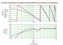
If you wish to use a 'traditional' (not mass-loaded) TL, you might want to taper the line and, if possible, offset the driver more. This will attenuate the higher frequency peaks slighly more.
What do you think about this sim?
Line parameters (TL Offset Driver.mcd):
Length: 70 inch
Offset: 18 inch
Driver end: 3.25 x Sd
Open end: 0.9 x Sd
Density: 0.35 Lb/Ft3
What do you think about this sim?
Line parameters (TL Offset Driver.mcd):
Length: 70 inch
Offset: 18 inch
Driver end: 3.25 x Sd
Open end: 0.9 x Sd
Density: 0.35 Lb/Ft3
Attachments
hey,
thank you arcturus, your ideas really work seems that tapered line works better in that case.
But what about "Helmholtz resonators" like here: http://www.visaton.de/english/artikel/art_585_6_20_2.html
"Two internal Helmholtz resonators are in use directly behind the woofer as sound absorbers and, in conjunction with the extremely carefully positioned damping material, will ensure that the frequency response is kept beautifully smooth."
thank you arcturus, your ideas really work
seems that tapered line works better in that case. But what about "Helmholtz resonators" like here: http://www.visaton.de/english/artikel/art_585_6_20_2.html
"Two internal Helmholtz resonators are in use directly behind the woofer as sound absorbers and, in conjunction with the extremely carefully positioned damping material, will ensure that the frequency response is kept beautifully smooth."
Greets!
For low Qt drivers, I prefer a well damped vent tuned pipe to get more gain than a 'classic' TL can provide:
L = 48.43"
SO, SL = 366.62"^2
rp = 3.416"
Lp = 0.75"
density = 0.3-0.4 lbs/ft^3 if polyfil
Due to the damping, driver position isn't too critical, so anywhere between ~10.25" - 21.25" down from the top.
GM
Greets!
For low Qt drivers, I prefer a well damped vent tuned pipe to get more gain than a 'classic' TL can provide:
L = 48.43"
SO, SL = 366.62"^2
rp = 3.416"
Lp = 0.75"
density = 0.3-0.4 lbs/ft^3 if polyfil
Due to the damping, driver position isn't too critical, so anywhere between ~10.25" - 21.25" down from the top.
GM
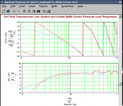
I suppose you meant it this way:
SO, SL = 36.662"^2
Port radius = 0,75"
Port length = 3.416"
I ran a sim with these values. Seems like a very good solution... It gives great extension with minimal ripple at high end. Great!
Attachments
GM:
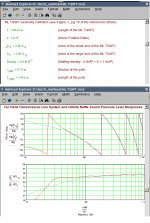
I didn't realize that your design uses a resistance port (Variovent?) at the TL's open end. Perhaps that's why I got a SPL peak at ~38Hz of about 8dB magnitude in my simulation. (ML-TQWT.mcd)
But don't you think it's quite a big enclosure needed for this?
I've never seen a "restrictive port" used with a TL-enclosure. I've seen that technique used only with sealed enclosures, that's why I didn't understand you at first. I'm sorry
Greets!
No problem, you made a reasonable assumption based on 'classic' TL design thoughts and the sims. Sure you have! A reverse tapered TL is a restrictive (mass loaded) port alignment, I just kept it simple to build. Add enough stuffing and it's ~aperiodic (aka resistive, Variovent loaded), so to compensate for the damping, more box efficiency is required to boost it back up just as the sim predicts.
GM
I know this is an old thread, but how did it pan out ?...... I'm looking to use the same mid driver, as I want the best mid I can get, and it seems to well recommended. Plus the idea of TL to give that uncoloured and open sound appeals as well....
So looking to build the same !
So looking to build the same !
look at is big brothers http://www.humblehomemadehifi.com/download/Humble Homemade Hifi_Optimo.pdfHello,
new year, maybe more ideas... Still looking for a best (TL) design for my drivers
Maybe someone have something interesting in mind...
Thanks
- Home
- Loudspeakers
- Multi-Way
- Building Transmission Line for SS 15W8530K00