WOW! The modified Thor design (AKA Fat Thor) can really belt out the low notes. Amazing difference. They sound fuller with much deeper bass.
I still need to make some stuffing adjustments, but I think I will be staying with the Fat Thors.
Although my speaker placement is a little odd, the room can easily accomodate these speakers. They are not as imposing as I thought they would be.
Anybody wishing their Thors had a little more umph on the lower end should definetly look into building a Fat Thor pair.
I'm anxious to see what the measurements look like once someone with the necessary equipment builds a set.
Thanks to everyone who contributed to the design.
Regards,
Rep
I got to "run" by Reputes Friday for 20-30 minutes.
Totally different speaker.
I did not get to put them through their paces, but you could immediately hear the obvious... WAY lower bass output.
But to my delight was the mid-bass. The lacking snap of his old spkrs were definitely gone now. Snare drum and wood block percussion were much improved. They are now to a point where I might consider owning a pair. We need to do more experimenting in elevation of the box and stuffing, but all in all, VERY worth the effort.. And they aren't even mine.
That's interesting - I got my 'Odins' setup two days ago and we listened to a movie. The Odin is the center speaker, with the original Thor's as the left and right front speakers. The Thors sound much better than the Odin, frankly, but I haven't done any really critical listening tests.
I have the MDF but haven't had time to cut it up yet. I have the drivers on quick connects so my hope is to just move over the xover and drivers to the fat thor.
The Fat thor is a different architecture though, it's not just a fatter Thor. If you look at the driver placement, I think it's at a different place in the line. I'm not saying it's not correct, it's just different.
jgwinner said:The Fat thor is a different architecture though, it's not just a fatter Thor. If you look at the driver placement, I think it's at a different place in the line. I'm not saying it's not correct, it's just different.
Dave has based the altered geometry of the Fat Thor on Martin King's alignments, which are more refined and considerably more accurate that the original Ausberger tables d'Apolito used. If you're going to optimise a cabinet for these expensive drivers, you might as well do it properly, and incorporate all the refinements you possibly can. The Short Thor MLTL also originated in Martin's work, this time his seminal MathCad worksheets.
Best
Scott
Scottmoose said:Dave has based the altered geometry
Understood, but to be pedantic that's not quite what I said. Ne altered the architecture, not just the area / length of the line.
The original Thors have the driver located at the 'fat end' of the tapered pipe. These have the drivers located more in the middle.
In Dave's variation the drivers are at the middle of the second quarter; the original Thors the drivers are in the middle of the first quarter (counting from the big end).
http://www.seas.no/thor.htm
I'm not saying it's better or worse, but it is different. This isn't a 'fat thor' it's a 'fatter and slid thor'

Does it matter where in the line the drivers are?
Yes, offsetting the drivers from the closed end of the line is a key factor in controlling the ripples caused by the higher pipe modes. Most people offset the drivers between 1/5 and 1/3 of the total line length, but even just a little offset will have a big benefit. There is not one theoretically perfect offset, just different compromises.
jgwinner said:He altered the architecture, not just the area / length of the line.
The original Thors have the driver located at the 'fat end' of the tapered pipe. These have the drivers located more in the middle.
In Dave's variation the drivers are at the middle of the second quarter; the original Thors the drivers are in the middle of the first quarter (counting from the big end).
Not really. In the original Thors there is an offset -- the effective position of the driver is right where the tweeter is. I just moved the offset so that it does a better job of killing the 1st unwanted harmonic. That this was far enuff along the line so that the box could be flipped & get a bottom exiting terminus as a bonus.
The Fat Thor is pretty true to the Thor*. Same topology, just some optimization thru use of techniques now understood much better becasue we can see and experiment with what they do without building a box using Martin's software.
* (if any change in "architecture" it is the restricted terminus introduced by Scottmoose to help allow a size reduction from the original concept -- if you want to stay totally true to the architecture you would go with the alpha of the Fat Thor -- which we can call the Extra Fat Thor)
The box was made adequately large, the offset was moved to a choosen spot instead of one arbitrarily determined by typical MTM driver placement, and a restricted terminus (ML=mass loading) is utilized to further improve the low pass filter characteristic of the line.
dave
Re: Driver allignment.
Tweeter height is usually considered optimum at about 36" but often will be lower. There is a note about a pedistal. This could lift the speaker the required 6" or it could just accomodate a bit of back tilt to fire the tweeters at your head.
dave
Luke said:I just looked at the drawing for the new fat thor cabinet, and noticed that the tweeters are at around my chest height when Im seated. Should they not be around ear height?
Tweeter height is usually considered optimum at about 36" but often will be lower. There is a note about a pedistal. This could lift the speaker the required 6" or it could just accomodate a bit of back tilt to fire the tweeters at your head.
dave
Yep. A pedistal is required to raise the port off the floor and bring the tweeter to ear level... The drawings do have a note at the bottom regarding this...
Regards,
Rep
http://www.diyaudio.com/forums/attachment.php?s=&postid=770729&stamp=1132458548
Regards,
Rep
http://www.diyaudio.com/forums/attachment.php?s=&postid=770729&stamp=1132458548
You'll also note that the original has pretty much the same issue.
I include driver positions in the phrase 'geometry' by habit, though I should perhaps have made that clearer. Sorry for any confusion, though I think Martin and Dave have covered that all in depth now.
Cheers
Scott
jgwinner said:Understood, but to be pedantic that's not quite what I said. Ne altered the architecture, not just the area / length of the line.
I'm not saying it's better or worse, but it is different. This isn't a 'fat thor' it's a 'fatter and slid thor'
I include driver positions in the phrase 'geometry' by habit, though I should perhaps have made that clearer. Sorry for any confusion, though I think Martin and Dave have covered that all in depth now.
Cheers
Scott
Please note that Reputes' were raised from the plans by NOT cutting the panels to length and leaving the sheet of MDF @ 49 inches.
We simply put in a false floor which also gives a chamber for the cross-overs too.
After hearing the new boxes briefly I would have liked to experiment with front terminus via a longer 4" pipe through the divider and front panel.
Then the boxes would be much less affected by boundaries and more flexible placement.
Reputes have tremendously more bass output and there is no way he could put them near a rear wall or heaven forbid a corner. But then every room is different and they could be moved and adjusted to taste.
ZDR - This quote from Planet10 earlier I think answers your question - " and a restricted terminus (ML=mass loading) is utilized to further improve the low pass filter characteristic of the line."
This also has an effect on the line length and has allowed the design to be shortened.
RABSTG - A longer 4 Inch Pipe is no longer a 4 Inch Pipe
EVERYBODY - I am considering this down firing port. Is there a minimum distance that needs to be taken into account? Is there a minimum area for the opening of the "chamber" beneath the port?
Does anybody have examples of nice looking integral / non integral pedistals?
Byrd said:Does anybody have examples of nice looking integral / non integral pedistals?
An externally hosted image should be here but it was not working when we last tested it.
An externally hosted image should be here but it was not working when we last tested it.
dave
RABSTG - A longer 4 Inch Pipe is no longer a 4 Inch Pipe
The current design states 3" dia and 4" long.
I meant 4" dia and x long (larger dia requiring longer length).
But I laughed at my self regardless. Thanks..
EDIT:
Does anybody have examples of nice looking integral / non integral pedistals?
Repute has some nice bases under his, but with the down firing port they may need longer spikes.
Hey Guys
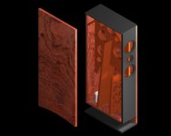
Would a pedistal arrangement such as the one depicted be ok?
* Both Front & Back are open.
Would it be permissable to have just the back open?
One thing that I realised is that it would probably be easier to keep the front to back brace in one piece and then route a slot in the box divider for the line for the brace to fit into it.
Attachments
Byrd said:Would a pedistal arrangement such as the one depicted be ok?
As long as the cavity is large enough it shouldn't be a problem. If it isn't you might get some resonances that may be problematic (1/2 wave with both ends open, 1/4 wave with only 1. If you are going to close off the front, it might be an idea to also put a partition just in front of the port to make the cavity length quite small.
If you do leave it open, remember to put cardboard or something for the cats to lie on
dave
PS: I might tap you for some 3D renders for the aXp (in the works) article on Fat Thor... can you do a render on a white background?
- Home
- Loudspeakers
- Multi-Way
- Clarity on Seas Thor Kit