Hi All,
I made a prototype enclosure (non ideal... long story) for my mtm project. Some of the acoustic measurements have been far from ideal.... one key thing with it was that I wanted to use a separate volume for each driver completely sealed. Therefore my enclosure has three completely separate volumes one for each mid bass and one for the tweeter.
Now the thing that bugs me about this is that in order to get the tweeter in close proximity to the midbass' The midbass drivers have to be mounted very close to the top/bottom wall of each drivers volume, and I'm not sure if this is a problem. I'm starting to think that maybe I should build a single volume enclosure. What I'm concerned about is strange reflections because of the close proximity to the wall.
One thing I have been thinking today is that maybe I should angle the partitions at 30 deg so that I end up with a rake back behind the driver (and non-parallel walls top-to-bottom internally).
not that it is probably relevant but the drivers are morel MW144's and DMS37.
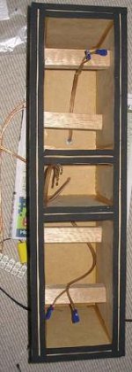
picture of prototype box attached, note that it is too narrow (175mm outer dimention for width) new box will probably be 225mm outer with 25mm chamfer on the baffle (using 25mm mdf). Arrived at after modelling in BDS.
So The question is: Is any supposed benefit of having separate volumes for the midbass units going to be canceled out (or perhaps made worse) because the drivers are mounted too close to the top (or bottom) sides of the separate volumes.
Tony.
I made a prototype enclosure (non ideal... long story) for my mtm project. Some of the acoustic measurements have been far from ideal.... one key thing with it was that I wanted to use a separate volume for each driver completely sealed. Therefore my enclosure has three completely separate volumes one for each mid bass and one for the tweeter.
Now the thing that bugs me about this is that in order to get the tweeter in close proximity to the midbass' The midbass drivers have to be mounted very close to the top/bottom wall of each drivers volume, and I'm not sure if this is a problem. I'm starting to think that maybe I should build a single volume enclosure. What I'm concerned about is strange reflections because of the close proximity to the wall.
One thing I have been thinking today is that maybe I should angle the partitions at 30 deg so that I end up with a rake back behind the driver (and non-parallel walls top-to-bottom internally).
not that it is probably relevant but the drivers are morel MW144's and DMS37.
picture of prototype box attached, note that it is too narrow (175mm outer dimention for width) new box will probably be 225mm outer with 25mm chamfer on the baffle (using 25mm mdf). Arrived at after modelling in BDS.
So The question is: Is any supposed benefit of having separate volumes for the midbass units going to be canceled out (or perhaps made worse) because the drivers are mounted too close to the top (or bottom) sides of the separate volumes.
Tony.
Attachments
If the drivers will be wired in parallel and the baffle step compensation will affect both drivers, a single chamber will be fine. In other words, two chambers are not required if it's a normal 2-way crossover.
If the MTM is a crossed over in a 2.5 way format, the woofers should have separate chambers. Not doing so results in slightly ragged response in the lower midrange because the driver's back pressure is different between 200 and 1000 due to BSC. Most 2.5 ways are TMM format though, so this may not be a problem.
The issue you mention about having walls in close proximity to to a driver has never caused much of a problem for me. In fact, I once used a 5" tube for a midrange enclosure, and with a good amount of damping at the back, the response was very smooth.
Anyway, I'm doing sort of the same thing with an MMTMM, and the outside woofers have a wall in close proximity to the driver. The outside drivers are the ".5" in a 2.5 way, and they need separate enclosures to avoid driver interaction in the 200-1000 range.
Attachments
Thanks Zaph ") I wasn't planning on doing a 2.5 way, but since doing the separate chambers isn't that much extra work, and it sounds like I shouldn't worry about the proximity of the driver to the edges, I think I'll go ahead with separate volumes, as it gives me the flexibility to change if I want
I wasn't planning on doing a 2.5 way, but since doing the separate chambers isn't that much extra work, and it sounds like I shouldn't worry about the proximity of the driver to the edges, I think I'll go ahead with separate volumes, as it gives me the flexibility to change if I want
I was planning on having an external crossover with separate binding posts for each driver to give me the most flexibility, so I can change to my hearts content, or even go fully active If I feel then need.
Thanks for the response plot too! I'm curious now whether the differences I'm seeing are baffle related or driver related (I suspect baffle)... at least some of it seems to match up reasonably well with sims in BDS. I think I'll take a measurement with a driver sitting on the floor pointing up, and see what the higher frequencies look like.
I've got some serious doubts about my accoustic measurements, I'll do some new ones when I get to my parents place where I'll hopefully have a better environment for testing!
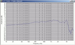
Here is the gated response I took the other day... nearfield is spliced in but at the resolution of the gated, so is a bit useless
edit: my drivers are a little closer than in your plans there is about 1mm between the cutout of the MW144 and the top of the box I think I might laminate two pieces of 18mm MDF leaving it at only 16mm thick at the tweeter end, that should give me a bit more space whilst still having a solid partition, and being able to get the tweeter and mids close enough together.
Tony.
PS. I notice your flares at the back of the drivers cutouts, I'm planning on doing this as well, but wasn't sure to what extent I should do it. I'll have 25mm baffles, do you flare right from the front, or do you leave a step?? _/ or just / if you get my meaning
_
\ \
I wasn't planning on doing a 2.5 way, but since doing the separate chambers isn't that much extra work, and it sounds like I shouldn't worry about the proximity of the driver to the edges, I think I'll go ahead with separate volumes, as it gives me the flexibility to change if I want I was planning on having an external crossover with separate binding posts for each driver to give me the most flexibility, so I can change to my hearts content, or even go fully active If I feel then need.
Thanks for the response plot too! I'm curious now whether the differences I'm seeing are baffle related or driver related (I suspect baffle)... at least some of it seems to match up reasonably well with sims in BDS. I think I'll take a measurement with a driver sitting on the floor pointing up, and see what the higher frequencies look like.
I've got some serious doubts about my accoustic measurements, I'll do some new ones when I get to my parents place where I'll hopefully have a better environment for testing!
Here is the gated response I took the other day... nearfield is spliced in but at the resolution of the gated, so is a bit useless
edit: my drivers are a little closer than in your plans
there is about 1mm between the cutout of the MW144 and the top of the box I think I might laminate two pieces of 18mm MDF leaving it at only 16mm thick at the tweeter end, that should give me a bit more space whilst still having a solid partition, and being able to get the tweeter and mids close enough together.Tony.
PS. I notice your flares at the back of the drivers cutouts, I'm planning on doing this as well, but wasn't sure to what extent I should do it. I'll have 25mm baffles, do you flare right from the front, or do you leave a step?? _/ or just / if you get my meaning
_
\ \
Attachments
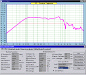
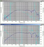
On the subject of sus acoustic results, I've attached two nearfield tests that I did. One was a while back, and the other I did just the other day. The top one looks very good to me, the second one looks very similar, but the thing that is bugging me is the phase reversal at 300Hz.... I'm planning on crossing these at 300Hz (I'll have a pair of stereo subs), and the first graph shows 0 deg at that point but on the second it looks like it would be the worst possible cross point phase wise.
What would be the likely cause of the differences in the two measurements. Both were done using speaker workshop and a WM60AY (un-modified) mic with Wallin II preamp. I only got good results like the top graph for a very short while, and since then I've had varying results (although it is now giving results like the second graph consitently after making a new preamp).
Tony.
Attachments
re enclosures
The principle I use is that stuffing materials have an acoustic absorbtion that is by a conservative approximation 150db. per metre over the range from severel hundred to several thousand cycles.
In order to get an average of 60db. attenuation of the back radiation the mean path length in the rear enclosure should be at least 0.4 metres. For a 6inch driver a 1:1.2:1.6, proportioned box of around 20 litres with the driver mounted in the center of one of the sides just about meets this.
Thanks RCW
I'm going to struggle to get a depth of 40cm though!!! I've only got 5L to play with!!!
My existing prototype cabinet has an internal dimentions of depth 220mm width 125mm, height 235mm (about 6.5L). The box was made to fit the baffle (which was originally made only to test out a circle jig I made and to test flush mounting of the drivers. I don't have the woodworking tools, so I did the baffle at my Parents place which is about 550KM away. When I returned home I got some MDF cut to match the (not really thought out) baffle, and made the test box.
The peakyness in the response curves (nearfeild) above *are* due to rear relfections, these were with some stuffing, they are much bigger without it.
Unfortunately I think I'm going to have to increase the baffle width, which means my depth will go down some more... though maybe I need to rethink the 125mm depth!! I was striving to have the depth the longest dimention but am a bit stuck at the moment. Maybe I should look at what dimentions I'd get with a common volume, might be better overall, and allow me to get a better depth! I guess the other thing is I should not worry so much about the golden ratio's, the dimentions I had for the new volumes was 175W X 237 H X 125 D which is about 5.2L That is a 1 : 1.4 : 1.9 ratio. The woofers will fit on a 125mm (internal width) baffle as I'm using 25mm mdf (this is what my prototye has) but I think it is too narrow, and It doesn't give me enough room for doing a chamfered edge.
arrhhhgggg I've just had the thought maybe I should forget the chamfer and use felt..... I need to semi finalise this design by the end of the week
actually I guess I could manage swapping the height and depth.... I'd end up with some really short deep cabinets though!! would need to do some stands though to get them high enough for ear height listening, or change the height of my subwoofers a bit.....
Tony.
I'm going to struggle to get a depth of 40cm though!!! I've only got 5L to play with!!!
My existing prototype cabinet has an internal dimentions of depth 220mm width 125mm, height 235mm (about 6.5L). The box was made to fit the baffle (which was originally made only to test out a circle jig I made and to test flush mounting of the drivers. I don't have the woodworking tools, so I did the baffle at my Parents place which is about 550KM away. When I returned home I got some MDF cut to match the (not really thought out) baffle, and made the test box.
The peakyness in the response curves (nearfeild) above *are* due to rear relfections, these were with some stuffing, they are much bigger without it.
Unfortunately I think I'm going to have to increase the baffle width, which means my depth will go down some more... though maybe I need to rethink the 125mm depth!! I was striving to have the depth the longest dimention but am a bit stuck at the moment. Maybe I should look at what dimentions I'd get with a common volume, might be better overall, and allow me to get a better depth! I guess the other thing is I should not worry so much about the golden ratio's, the dimentions I had for the new volumes was 175W X 237 H X 125 D which is about 5.2L That is a 1 : 1.4 : 1.9 ratio. The woofers will fit on a 125mm (internal width) baffle as I'm using 25mm mdf (this is what my prototye has) but I think it is too narrow, and It doesn't give me enough room for doing a chamfered edge.
arrhhhgggg
I've just had the thought maybe I should forget the chamfer and use felt..... I need to semi finalise this design by the end of the week actually I guess I could manage swapping the height and depth.... I'd end up with some really short deep cabinets though!! would need to do some stands though to get them high enough for ear height listening, or change the height of my subwoofers a bit.....
Tony.
rear chambers
The other thing you can do is to make the enclosure minimum size so that it has a resonant frequency the same as your lower crossover frequency.
I did this for my midrange waveguides, the result is that the average path is around 25-30mm. so the first enclosure resonance is above the upper crossover frequency.
The difficulty is that this increases Qt, I used a passive circuit published by Thiele to correct this, you can also use a Linkwitz transform circuit.
hmmm I think I'll do some calcs and see what I come up with .. I'd like to leave these drivers so that can play all the way down, I will be doing the subs (probably) separately, and it could take a while (not to mention I have to build another amp and active crossover as well.....) They don't have strong bass below about the 100Hz mark but it isn't too bad, and I think I could cope with it for a while at least even in the very raw form at the moment it is better than my existing 3 ways... so the potential is there!
I was doing some experiments to try and tame the rear reflections, I've managed to attenuate them quite a lot but not to eliminate them, about half way through the tests I started getting really inconsistent results and stopped.... I think I'm getting my measurements back on track now, but I still have some issues with them.
Might need to build another test box before I finalise the design
Tony.
.. I'd like to leave these drivers so that can play all the way down, I will be doing the subs (probably) separately, and it could take a while (not to mention I have to build another amp and active crossover as well.....) They don't have strong bass below about the 100Hz mark but it isn't too bad, and I think I could cope with it for a while at least even in the very raw form at the moment it is better than my existing 3 ways... so the potential is there!I was doing some experiments to try and tame the rear reflections, I've managed to attenuate them quite a lot but not to eliminate them, about half way through the tests I started getting really inconsistent results and stopped.... I think I'm getting my measurements back on track now, but I still have some issues with them.
Might need to build another test box before I finalise the design
Tony.
- Status
- This old topic is closed. If you want to reopen this topic, contact a moderator using the "Report Post" button.
- Home
- Loudspeakers
- Multi-Way
- separate or combined volumes for MTM project