I just recently built myself a microphone and have been reading Joseph D'Appolito's book Testing Loudspeakers. So of course I started testing my speakers right away. I built these speakers based on simulations and lots of listening. But now that I've started testing them I see that the simulations have been a little misleading.
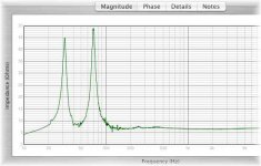
I thought I had a second order L-R crossover at 300Hz. I've measured the impedence and it's pretty steady around 7ohms from 150Hz on with the Zobel network attached. I'm using a 7.5mH inductor with a 39uF capicitor shunted. Looking at the measurements it does not look like it reaches -6dB until almost 500Hz. For kicks I measured with just the 7.5mH inductor (and zobel), which should give a first order crossover. However this is not down a single dB at 150Hz and does not reach -3dB until 300Hz.
Can anybody give me any insights into why this would be? I'll attach the measurement pictures and impedence plots.
Thanks
Joe
Attachments
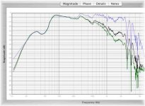
Well your 1st order is ok, it's 3 dB down at 300 Hz like it should be.
Your 2nd order should be 6 dB down at 300 Hz.
You could look at the Impedance phase plot to see the problem.
Only thing I see it's your capacitor value is slightly too high, should be around 37-38 µF but that should not be a problem.
Maybe measure the capacitor value?
Maybe wrong wiring?
Your 2nd order should be 6 dB down at 300 Hz.
You could look at the Impedance phase plot to see the problem.
Only thing I see it's your capacitor value is slightly too high, should be around 37-38 µF but that should not be a problem.
Maybe measure the capacitor value?
Maybe wrong wiring?
It looks like you simply used textbook equations to work out those component values. You'll need to optimize those values based on both the impedance curve and raw acoustic output of your driver(s); against a target function. In this case the target transfer function is a low-pass LR curve. Remember to calibrate everything...
")
f4ier said:It looks like you simply used textbook equations to work out those component values. You'll need to optimize those values based on both the impedance curve and raw acoustic output of your driver(s); against a target function. In this case the target transfer function is a low-pass LR curve. Remember to calibrate everything...
That is true.
I haven't seen that crosseyed doggie picture for some time now.Josephjcole said:I just recently built myself a microphone and have been reading Joseph D'Appolito's book Testing Loudspeakers. So of course I started testing my speakers right away. I built these speakers based on simulations and lots of listening. But now that I've started testing them I see that the simulations have been a little misleading.
I thought I had a second order L-R crossover at 300Hz. I've measured the impedence and it's pretty steady around 7ohms from 150Hz on with the Zobel network attached. I'm using a 7.5mH inductor with a 39uF capicitor shunted. Looking at the measurements it does not look like it reaches -6dB until almost 500Hz. For kicks I measured with just the 7.5mH inductor (and zobel), which should give a first order crossover. However this is not down a single dB at 150Hz and does not reach -3dB until 300Hz.
Can anybody give me any insights into why this would be? I'll attach the measurement pictures and impedence plots.
Thanks
Joe
Why does the FR look like to one you posted for MLTR tuning?

Re: Re: crossover simulation/measurement question
This sounds good, but unfortunatly I don't know how to come up with cross-over values other than finding out the impedence at the crossover point and plugging them into the "textbook equations". What would you recomend, or do you have some suggested reading/links?
Because it is the same speaker. An 12" eminence crossed over to a 4" fostex, and now that I've started measuring I had a couple of questions. I didn't think crossover questions belonged on the fullrange forum.
Joe
f4ier said:It looks like you simply used textbook equations to work out those component values. You'll need to optimize those values based on both the impedance curve and raw acoustic output of your driver(s); against a target function. In this case the target transfer function is a low-pass LR curve. Remember to calibrate everything...
This sounds good, but unfortunatly I don't know how to come up with cross-over values other than finding out the impedence at the crossover point and plugging them into the "textbook equations". What would you recomend, or do you have some suggested reading/links?
soongsc said:
Why does the FR look like to one you posted for MLTR tuning?
Because it is the same speaker. An 12" eminence crossed over to a 4" fostex, and now that I've started measuring I had a couple of questions. I didn't think crossover questions belonged on the fullrange forum.
Joe
What would you recomend, or do you have some suggested reading/links?
Speaker Workshop will do what you need, and IMO is your next logical step after aquiring measurement capability. Of course you could also go with something like lspcad or soundeasy, but SW is free.
Josephjcole said:Unfortunatly I'm on a Mac so I don't have access to these programs. I've looked around a bit for software that can run these kind of functions on the Mac, but have not found anything. Is there any good way to go about it with out simulators?
thanks
Joe
Someone using a PC was trying to find FuzzMeasure (runs on mac). Are Excel spreadsheets interchangeable between PC and Mac?
soongsc said:Are Excel spreadsheets interchangeable between PC and Mac?
Not interchangeable but you can buy the app. as part of the ms office suite made for macs.
Joe,
Way back when you were putting these together I suggested an inexpensive plate amp and electronic crossover. In part that suggestion was made to prevent what has happened. Passive speaker level crossovers are not easy and rarely test as simulated.
Are you serious about this inquiry? If so, e-mail me through this site and include your e-mail addess. Let us take this conversation private for a while.
Mark
You already have measurement capability. All you really need now is a filter simulator which is capable of taking those measurements into account during simulation. As was suggested, you could use Speaker Workshop. SW's filter simulator should run without any problems, but its measurement functions may not run at all due to possible hardware access issues with VirtualPC... I guess trying is the only way to find out for sure.
You could use Crossover Simulator if for some reason SW won't run at all under VirtualPC. I remember at least one Mac user who reported no problems whatsoever with VirtualPC + XoverSim. Its textual circuit schematics entry may not make sense initially though... Le'me know if you need help.
You could also try Jeff's Excel spreadsheets. I don't know if Jeff coded them with VBA, and if VBA code runs on Mac versions of Excel, I guess you can only try as well. Anyone know if VBA code is actually interpreted or if an executable is actually compiled and linked for the spreadhseet? You can find them, and some more free tools, at the FRD Group site. The site also has great articles.
All of the above-mentioned software take your measurements in the form of FRD Files. Aside from MATLAB, which is very expensive and overkill, I don't know of any other Mac compatible software capable of handling these FRD files.
Mark's suggestion will get you there but be careful with what you get/build. If this hasn't been brought up yet... Electronic filters are no more easier to implement than passive ones. Sure, one can disregard impedance curves when it comes to electronic filters, but having a textbook electrical transfer function (which is what one gets with active filters) doesn't necessarily give us an ideal acoustical transfer function as well. Either way, we don't care about the electrical curve (so long as your amps can handle the finished speakers), we only care about the acoustical response. Your current passive crossover is another example of this point.
If you were going to go ahead with electronic filtering, the gear would have to be similar to the Behringer DCX2496.
The Loudspeaker Design Cookbook might help clear things up, but first you've got to find a Mac compatible crossover simulator.
Thanks everybody for the responses.
simon5- the impedence and frequency plot was in my first post.
MarkMcK- Impressvie memory. I acctually followed your advice and bought a cheap plate amp. Unfortunatly I think the fostex needs to be crossed over higher than the plate amp goes (180Hz). On top of this my cheap plate amp ended up being +5dB @ 40Hz. A sort of built in "bass boost". Anyways I switched to a passive crossover and am aiming for a 2cnd order acustic crossover at 300Hz. The fostex starts a slow roll off around here anyway so a first order does the trick pretty well on that one. It's the Eminence that's giving me trouble.
f4ier- Maybe I'll break down and get myself a copy of VirtualPC. I've tried the FRD group Crossover Simulator, but it didn't work on my Mac.
Re: Re: Re: crossover simulation/measurement question
http://www.mhsoft.nl/spk_calc.asp
Josephjcole said:
This sounds good, but unfortunatly I don't know how to come up with cross-over values other than finding out the impedence at the crossover point and plugging them into the "textbook equations". What would you recomend, or do you have some suggested reading/links?
Because it is the same speaker. An 12" eminence crossed over to a 4" fostex, and now that I've started measuring I had a couple of questions. I didn't think crossover questions belonged on the fullrange forum.
Joe
http://www.mhsoft.nl/spk_calc.asp
f4ier-
how is MATLAB? Is it something that I could figure out (keeping in mind I'm somewhat thickheaded at times)? My sister-in-law is working on her Doctorate in Mathmatics, and I believe she has a copy I could use. That way I wouldn't have to buy any software.
rnrss- this is the calculator I used, but as you can see it didn't work out so well....
Joe
MATLAB will handle this sort of thing very easily. If you have a look at a description of an FRD file in the link above, you'll see that an FRD file is nothing more than a text file containing each and every data point on those graphs.
Basically... Just read-in the files into MATLAB, write the transfer function [of a second order circuit in this case] that would use the measured impedance as the load, fill in the values for the cap and inductor then calculate away. Multiply the filtered electrical frequency response with the raw driver acoustical response then you have yourself an accurate simulation; that is if your measurements were properly done. It should only take your sister-in-law several minutes to cook up a simulator with a simple graphical user interface and all for you.
If you know how to analyze circuits by hand, then learning how to use MATLAB to do all the dirty work for you should be quite straight forward.
- Status
- This old topic is closed. If you want to reopen this topic, contact a moderator using the "Report Post" button.
- Home
- Loudspeakers
- Multi-Way
- crossover simulation/measurement question