If you have a problem getting the voltage curve at the driver terminals that you need, then add the type you need, but not as a matter of course.
Is it possible to elaborate with example. Or direct to some link.
I'll elaborate.
The only specific cases where I've needed to flatten impedence was when making 3 way crossovers and a fairly low crossover point to a vented woofer. That meant that the upper motional impedance peak was an Octave or so from the crossover point. A big inductor for rolloff was interacting with the impedance and gave a significant bump. An RLC network flattened the impedance bump and got rid of the interaction.
Regarding inductance rise and its cancelation, when I rolloff woofers with a lot of inductance I tend to use damped second order networks. That means a series inductor and a shunt combo of capacitor and resistor in series. That may look like a Zobel but unless the component values are just right then it is more proper to call it a damped 2nd order. I optimize to a response shape I need and don't look at the effect of R and C on impedance.
For tweeter networks, with lower order networks the tweeter's impedance bump at resonance can be seen in the terminal volts. This may be a problem with first order networks, but I never use first order. With second order it is less of a problem and with third it is no problem.
I can't imagine any reason to conjugate out the inductance rise of a tweeter. It is well removed from the crossover point so it will have virtually no effect on frequency response. If I want response shaping in that area I will tackle it directly.
David S.
Tweeter zobel network
When the tweeter level is reduced with a series resistor I have on occasion added a zobel like network to a tweeter, for the reason of reducing the tweeters inductive rise in impedance.
This only works when the tweeter is connected to a series resistance to reduce its output (to match the efficiency of the bass circuit).
With no series resistance or with an active crossover all the zobel does is load the amp un-necessarily.
Maybe it isn't "needed" but for whatever reason sometimes a speaker that uses one just works "Better"
When reading the LDC section on crossovers it is states quite clearly that his advice on designing cross-overs only applies to drivers which have had their impedance corrected to "Flat" and I interpret this to mean ALL of the drivers; tweeters included.
As I said earlier, I have used it with one particular cheaper tweeter and for what ever reason it worked to improve the cohesion.
Which BTW was first on the midrange and second on the tweeter
I notice that most people do not use Vifas recommended compensation network on tweeters either which is an RLC network very low
Last edited:
Can you please post exact link to this article.
Hi Aucosticraft, here is a link to where the OP came from, note it really doesn't have any more info. LDSG - Morel recommendations
and now for some general ramblings on the original topic: If you think about what happens with a zobel, as the freq rises the inductance increases, making more of the energy take the path of the cap and resistor the higher the inductance the more energy will be dissipated in the resistor, so in the case of a tweeter with an increase in spl as frequency increases (which the Morel MDT33 doesn't!) then I guess it could be seen as a frequency dependant attenuator... I can't see any reason why you would do it on an MDT33 unless you like a decrease in spl as freq rises
")
Tony.
Hi Aucosticraft, here is a link to where the OP came from, note it really doesn't have any more info. LDSG - Morel recommendations
and now for some general ramblings on the original topic: If you think about what happens with a zobel, as the freq rises the inductance increases, making more of the energy take the path of the cap and resistor the higher the inductance the more energy will be dissipated in the resistor, so in the case of a tweeter with an increase in spl as frequency increases (which the Morel MDT33 doesn't!) then I guess it could be seen as a frequency dependant attenuator... I can't see any reason why you would do it on an MDT33 unless you like a decrease in spl as freq rises
Tony.
Well Tony some may actually be able to hear that high. in which case the tweeter may sound "Sweeter" or less shrill? but what you say makes very good sense; the tweeter that responded well to the Zobel did have a rising response as it passed 22k
Peerless 810921 zobel
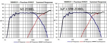
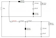
I've used a zobel to good effect on a Peerless 810921 tweeter in an AR Series crossover. The plot on the left has no zobel and the one on the right has a zobel. In effect it causes a drooping impedance (<4R from 10kHz - 20kHz) on the tweeter which stops the rising FR. Over the years I've found a lot of the Peerless tweeters have an rising FR when used in series and low order crossovers where other brands do not exhibit this trait.
I've used a zobel to good effect on a Peerless 810921 tweeter in an AR Series crossover. The plot on the left has no zobel and the one on the right has a zobel. In effect it causes a drooping impedance (<4R from 10kHz - 20kHz) on the tweeter which stops the rising FR. Over the years I've found a lot of the Peerless tweeters have an rising FR when used in series and low order crossovers where other brands do not exhibit this trait.
Attachments
Maybe it isn't "needed" but for whatever reason sometimes a speaker that uses one just works "Better"
When reading the LDC section on crossovers it is states quite clearly that his advice on designing cross-overs only applies to drivers which have had their impedance corrected to "Flat" and I interpret this to mean ALL of the drivers; tweeters included.
As I said earlier, I have used it with one particular cheaper tweeter and for what ever reason it worked to improve the cohesion.
Which BTW was first on the midrange and second on the tweeter
There are many ways to approach x'over design and in the end, if something works it works. There seems to be a school that thinks that drivers should be conjugated to flat impedance, bass shelving circuits applied, then Butterworth, Bessel or whatever defined crossovers applied. The Elliot Sound Products page outlines this well. It is an aproach that tries to force a speaker to use what works with electrical filters and generally overlooks the reality of driver response.
This is neither the most efficient approach nor will it let you get to the best crossover shape. Better to think in terms of acoustic target functions: "Based on the delay between units and the desired crossover frequency, this woofer network needs this final shape, and the tweeter network this". If you have a total (network plus driver) target shape and you divide by the driver curve (divide with transfer functions or subtract with dB curves) the remainder is your electrical target function. The design objective is then to achieve the electrical target function with the minimum number of components in the most appropriate topology. Sometimes this will include network sections that "look like" conjugate sections, but a circuit is not a conjugate or Zobel unless it actually flattens impedance. With the approach I describe, flattened impedance, especially at an intermediate crossover point, is not a criterion.
If you use crossver design optimizers (I have used XOPT, LEAP Crossover Shop and the KEF system that predated all of them) then impedance conjugating doesn't enter in. Optimizers would warp conjugate values as needed to best hit the desired response shape.
It is true that conjugate sections might push the response in a desired direction, but constraining yourself to true conjugate values will seldom give optimum results and the conjugate topology will frequently be inappropriate.
David S.
David I recognize that what you say is "True" but for those of us who do not have access to or the funds to afford the programs and the associated measuring tools it is a rationale that works.
Yes yours is probably the preferred method and the only logical way to do things in a manufacturing system; but it is not the only way. By manipulation of Zobels ( or conjugate circuits ) we will often approximate a strange second order network via experimentation.
This is after all DIY Audio and experimentation is part of both the fun and the learning process.
All of the above said with the proper level of respect too, as it should be.
You are right that a DIY approach may generally be different than a commercial approach. As is said, there are many ways to achieve a result.
I didn't mean to be pedantic, but it gets frustrating when you see the myths spread about "always Zobel first" or "always add baffle compensation".
David S.
I didn't mean to be pedantic, but it gets frustrating when you see the myths spread about "always Zobel first" or "always add baffle compensation".
David S.
Hi Ted,
I nearly made a comment about how I originally tried a zobel on my MW144's but didn't like it, and in the end used the optimizer in speaker-workshop to find a filter that gave me the response I wanted (or close enough) without having to use zobels, but I deleted it before I posted.
David has articulated it much better than I could have!!
I found that the crossover simulator in speaker workshop is powerful, accurate, and best of all free
Combined with Holm impulse, also free (I only use speaker-workshop for impedance measurements now), a good measurement mic and preamp, and perhaps the walin jig II you have a very nice set of tools which should help immensely (once the learning curve for all of them is gotten over) with crossover design.
The stumbling block is of course the hardware. If one is on a tight budget, you are probably looking at $100 minimum to get started which could be almost as much as the first project costs of some people starting out.
I am however a strong believer in having the right tools for the job, I learned that working on cars! Having the right tool can save so much time and frustration, that once you have it you kick yourself they you didn't invest in it earlier
Tony.
Better to think in terms of acoustic target functions: "Based on the delay between units and the desired crossover frequency, this woofer network needs this final shape, and the tweeter network this".
Well said David.
Well said David.
 Agreed. If you can't measure as you design your not in the game!
True, whereas there can be some guidelines, hard rules as such do not yeild the most optimum designs.You are right that a DIY approach may generally be different than a commercial approach. As is said, there are many ways to achieve a result.
I didn't mean to be pedantic, but it gets frustrating when you see the myths spread about "always Zobel first" or "always add baffle compensation".
David S.
I know this is an old thread but relevant to me at the moment. On the topic of zobel for tweeters, here's a thought.
The amplifier output in series with the crossover also in series with the driver forms a complex tank circuit when amplifier is running. We don't often think about it this way but it's possible that a Zobel on the tweet might be acting as damping on the entire crossover/speaker "tank"? Being wired in parallel it would probably only effect the tweet and any components between it and the "tank".
The amplifier output in series with the crossover also in series with the driver forms a complex tank circuit when amplifier is running. We don't often think about it this way but it's possible that a Zobel on the tweet might be acting as damping on the entire crossover/speaker "tank"? Being wired in parallel it would probably only effect the tweet and any components between it and the "tank".
Zobels generally reduce back EMF feeding into the amplifier. But it's design needs more consideration to provide optimum results.
Meaning they absorb some of the back-emf due to lower impedance/resistance than the amplifier? That's what I was thinking and it's that 'damping' effect that might be changing how the tweeter sounds. It's also possible back-emf from the woofer can cause the tweeter tank to excite and ring and the zobel damps it. One could test that theory by tapping on the woof and reading the tweet with a scope, or just listening.
It's also possible the zobel alters the resonance of any tweeter tanks.
Gets complicated in a big hurry.
I can see this thread wandering off into oblivion as usual...This is not often discussed, but I've been told that adding an R-C network to some tweeters helpd to refine their sound. I came across this on the LDSG:
"The MDT33 tweeter has a very devoted following. Some have also recommended the use of a Zobel to sweeten the top end."
Your thoughts/experiences?
TIA
Neil
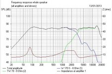
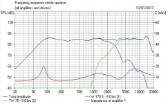
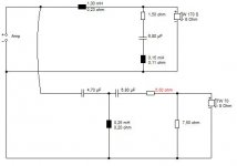
The simple answer is that a tweeter Zobel circuit can give a much better/higher impedance at the top end than an attenuator topology, which will make for a sweeter sound from most transistor amplifiers. Amps don't like supplying a lot of current quickly.
Typical Zobel values are 7.5R wirewound/1uF. This particular Visaton TW70 cone tweeter is 0.15mH Le so it's a bigger capacitor. But all things being equal, I'd go for the better impedance every time.
Impedance Equalization (L-Pad) Circuit Designer / Calculator
Attachments
- Home
- Loudspeakers
- Multi-Way
- Tweeter Zobel, or more accurately, RC network.