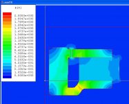
This is the nicest motor I have analyzed so far. I used 1008 steel and Ceramic 8 D in this simulation. Note that I get a maximum flux of 0.8 T in the gap. If the Seas data sheet (1.0 T) is accurate, this means they must be using even better iron and/or ferrite.
Attachments
flux lines
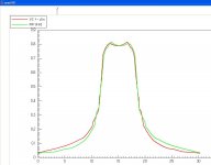
The coil in rest position extends from roughly 6 to 25 on the x-axis of above graph, with a nominal travel of +/- 6 mm.
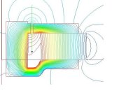
There would seem to be a slight assymetry in the fringe field that the coil would pick up while moving. However, looking at the flux line plot, we can see that the lines of the upper fringe field are nicely normal to the z axis, wheres the line in the lower fringe field are tilted. As only the normal component counts, we can expect the force curve to be even more symmetrical. I will report as soon as I have figured out how to operate the §()$/@!!! calculator...
I really wonder why Seas and so many other makers let the magnet extend substantially beyond the diameter of top and bottom plate. It seems all that flux is wasted.
The coil in rest position extends from roughly 6 to 25 on the x-axis of above graph, with a nominal travel of +/- 6 mm.
There would seem to be a slight assymetry in the fringe field that the coil would pick up while moving. However, looking at the flux line plot, we can see that the lines of the upper fringe field are nicely normal to the z axis, wheres the line in the lower fringe field are tilted. As only the normal component counts, we can expect the force curve to be even more symmetrical. I will report as soon as I have figured out how to operate the §()$/@!!! calculator...
I really wonder why Seas and so many other makers let the magnet extend substantially beyond the diameter of top and bottom plate. It seems all that flux is wasted.
Attachments
Thanks for the kind words, but all that is needed is to download Maxwell 9 SV from ansoft.com and work through the getting started guide which takes about an hour.
I gets more difficult when you want to use the advanced features which are not covered in that guide. The help pages are nearly like a manual, but unfortunately, only nearly.
Oh, and you need to dismantle a driver if you want to plan mods. With the Seas, it's a cinch. Just soak it in warm water for a couple of hours, then carefully peel off surround and spider. The back plate comes off easily after heating it on a ceramic kitchen stove for a couple of minutes. One could remove the back plate without removing the moving parts first, but putting things back together with the magnet still charged might result in a deformed VC former.
Hi,
can I assume the magnet is the blue cylinder in the middle (your right looking at the pic)?
Why the deep dish in the backplate? it seems to cause a bottleneck approaching 1.6T.
Your general shape more resembles the days of alnico and other expensive magnets
Why are the commercial ferrite and ceramic shapes (large magnet volume) so different from yours (small magnet volume)?
This is a rotational symmetric plot, and the center axis is on the left hand side of the picture. The magnet is the light blue thing on the right.
I may not have gotten the goemetry of the dish exactly right, but I do expect a slight bottleneck there (actually, 1.6 T is just the knee of saturation of 1008 steel). The dish is there to give the VC extra space for excursion. The line in the third picuture is the VC +/- nominal linear travel, but mechanical xmax is another 10 mm.
I may not have gotten the goemetry of the dish exactly right, but I do expect a slight bottleneck there (actually, 1.6 T is just the knee of saturation of 1008 steel). The dish is there to give the VC extra space for excursion. The line in the third picuture is the VC +/- nominal linear travel, but mechanical xmax is another 10 mm.
Hi,
what is 1008 steel?
Are there other suitable steels/irons? typeNo.?
Could you run a further simulation to see if it affects the gap flux?
try a 20% thicker backplate but increase the centre where it meets the centre pole by 40% i.e. tapered.
Now what if you machine a large countersunk hole in the rear face of the backplate, does it direct the flux more efficiently into the pole?
Thanks for confirming centre of rotation, now I can see it more resembles a typical ferrite assembly
npdang, who is also a poster in this forum, seems to have access to a Klippel system. He tested a Seas G18RNX/P, which uses the same motor I have simulated here:
http://www.diymobileaudio.com/forum/showthread.php?t=629&page=1
The Bxl curve looks surprisingly skewed. Note that my B plot only plots the magnitude of B along the gap. I really have to figure out how to plot the magnitude of B x z.
http://www.diymobileaudio.com/forum/showthread.php?t=629&page=1
The Bxl curve looks surprisingly skewed. Note that my B plot only plots the magnitude of B along the gap. I really have to figure out how to plot the magnitude of B x z.
- Status
- This old topic is closed. If you want to reopen this topic, contact a moderator using the "Report Post" button.
- Home
- Loudspeakers
- Multi-Way
- more field simulations: Seas L18 H1224 motor - WOW!