From sonicweld.com
I know absolutely nothing about crossover design....
Has anyone tried a x-over network like this? How would it be implemented? Were the results as claimed above?
Unique Crossover Design
Would you buy an amplifier with a large capacitor in the signal path of its output stage? Of course not. Why then accept one in the crossover of your speaker, which is nearly the same thing?
You don't have to anymore. Rarely does High End audio witness a true crossover innovation such as that featured in Sonicweld products. The same tired formulas, parts, and construction methods have been used for decades. Every conventional loudspeaker crossover uses reactive components (capacitors and inductors) in the signal path. Unfortunately, these filtering networks produce measurable and audible anomalies. Sonicweld circuits neatly sidestep these heretofore insurmountable problems by the use of a unique circuit with the following characteristics:
1. There are NO reactive parts in the signal path. The only element between the input terminals and the drivers is carefully-selected premium-grade wire, yet the driver array benefits from the electrical attenuation provided by conventional filter networks. The benefit to you: transparency, inner detail, speed, and the overall lack of noise and grain like you've never heard before. After extended listening to a Sonicweld speaker with this superior crossover, you may find it difficult and fatiguing to resume listening to the sonic atrocities introduced by conventional crossovers.
2. The Sonicweld crossover acts as almost a purely resistive load. Sonicweld speakers typically measure flat within ± .5 ohm to beyond their operating bandwidth. Your amplifier will perform much more effectively when driving an almost purely resistive load. This approach to crossover design eliminates reflections in the amplifier-to-speaker interface caused by reactivity, which is of particular benefit to tube amplifier owners.
3. All Sonicweld crossovers exhibit virtually no electrical phase shift. A variation of ± 5 degrees for their full bandwidth is typical.
I know absolutely nothing about crossover design....
Has anyone tried a x-over network like this? How would it be implemented? Were the results as claimed above?
By sonicweld There are NO reactive parts in the signal path. The only element between the input terminals and the drivers is carefully-selected premium-grade wire, yet the driver array benefits from the electrical attenuation provided by conventional filter networks.
Some linguistic trickery, plus perhaps some good engineering as well.
"Not in the signal path" has come to mean, in crossover circles, as "not in series with the driver". That still means the reactive component(s) can be hooked up in parallel to the drivers,and no doubt are.
If they can keep their speaker resistive or nearly resistive throughout the whole range, though, they have done a great job, even if they do play some games with the language.
")
Stocker said:Exactly. Note that inductors are reactive and made of wire only...
LOL
. But callling an inductor "a piece of premium grade wire" would really be cheating though. Although they may be doing it.Using reactive components only in parallel is just sort of taking advantage of a linguistic convention presently being used. Although that, too, is intended to mislead. Not as bad as calling an inductor a piece of premium wire, though.
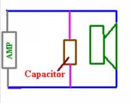
Below is a 6 dB low pass crossover. Things are not quite so simple as that, since at high frequencies this becomes a short circuit. However, other reactive components can be added in series with the capacitor to take care of that.
As long as none of the reactive components are in series with the driver, they theoretically are "not in the signal path".
Attachments
HOw have they done this? Lots of notch filters lol all set up to provide the desired roll off characteristic.
OK i tried this and its a no go, put one single capacitor in series and you can notch to your hearts content until you arrive at the desired filter characteristic. But you cannot get a parrallel trap to do anything unless there is a cap or coil in the way first.
It took 5 notches and a single cap to get 4th order linkwitz Riley on a scan speak d2905/95 at 3000hz. Anyone know how to get parallel components to work without a series?
5th element said:.....yeah its possible but its very complicated and uses a HUGE amount of components. But it can be done. Seems a bit of a stupid thing to do, might aswell just use an active xover.
For $40,000 a pair, you might wish consider it, yes.
It is even possible that they used a first order series network, which would theoretically satisfy the condition of no reactive components in the signal path, since it the signal played by the speakers theoretically has bypassed the reactive components and only gone through the drivers themselves.
This illustration is adapted from one on Rod Elliot's site. Here is the original illustration, (Rod's includes a parallel network for comparison purposes).
http://sound.westhost.com/par-ser-f11.png
http://sound.westhost.com/parallel-series.htm
This illustration is adapted from one on Rod Elliot's site. Here is the original illustration, (Rod's includes a parallel network for comparison purposes).
http://sound.westhost.com/par-ser-f11.png
http://sound.westhost.com/parallel-series.htm
Attachments
Thank you all for your replies! I am learning slowly the different crossover orders and what the circuit design to actual implementation looks like.
It was my interpretation of the site language that this implementation of the Seas EXCEL drivers had some no x-over voodoo going on. Which struck me as odd since from what I have read, the EXCEL speakers require some extensive x-over networks to make them sing.
Thanks again.
It was my interpretation of the site language that this implementation of the Seas EXCEL drivers had some no x-over voodoo going on. Which struck me as odd since from what I have read, the EXCEL speakers require some extensive x-over networks to make them sing.
Thanks again.
OK here is a simple setup of how this can work. The driver used was a seas excel W15CY001 I have measured myself. The dip at 1300hz is an artifact from the open baffle situation. This was a splice of near and farfield.
In the picture is the final result, what the speaker measured like before the xover, and then the schematic. As you can see there is a resistor of insignificant value at the start, LspCAD requires this to work properly with purely just parallel components.
I have not tried to simplify whats there, you can probably remove both the inductors if you want to and it will still work but I couldnt be bothered changing all the vaules in a new topology. I also didnt try to optomise this to give a sensable input impedance, the average with that xover is about 0.15ohms.
That is not the point though, the point is to say that it can be done but I dont honestly see why anyone would want to, as said before for that kind of money it makes sense to just use active xovers. Now-a-days people are much more used to the idea of an expensive speaker being active. I suppose for the company themselves its an excellent marketing point.
You can probably use just the capacitors now that I look at it again.
FWIW the xover is a 2nd order linkwitz at 2000hz.
Attachments
Bill Fitzpatrick said:With the series network, the L and C are still in the signal path.
So it is written in the audio texts.
However, considering the standards of audio advertisisng, "not having a reactive component in the signal path" might well be interpreted as, "Can you take a pencil and draw a line on the schematic from one end of the amp, through the speaker and over to the other end of the amp without passing through a capacitor or inductor?". Which you can do with a first order series crossover. Of course, you will pass through the other driver, but that counts a driver, not as a "reactive component".
I didn't know mass was reactive. I'll take your word for it.
Of course, every "normal" speaker is reactive because of it's voice coil, and will have an inductance, as well.
As for reactance being a good thing-wouldn't any reactance tend to throw the phase relationships of the music out of whack?
Of course, every "normal" speaker is reactive because of it's voice coil, and will have an inductance, as well.
As for reactance being a good thing-wouldn't any reactance tend to throw the phase relationships of the music out of whack?
You don't have to take anyone's word for it; you can see for yourself if you want. Plot the impedance of a speaker against frequency and note that it curves up (inductive) and down (capacitive) at various points. Now add some mass to the cone and plot impedance again. Note that the slopes have changed, i.e. the reactance has changed.kelticwizard said:I didn't know mass was reactive. I'll take your word for it...
Mass is the mechanical equivalent to electrical capacitance (and fluid tanks).
Mechanical dampers to electrical resistors (and fluid resistance).
Mechanical springs to inductors (and fluid inertance).
There are a few quircks in the math, with some equivalents being reciprocals in the "equivalent" form of the Diff. Eqations, but for the most part the analogy is very straightforward.
- Status
- This old topic is closed. If you want to reopen this topic, contact a moderator using the "Report Post" button.
- Home
- Loudspeakers
- Multi-Way
- purely resistive crossovers?