Hi All,
I'm considering tri-amping my current speakers, and thought that as a starting point I ought to determine the crossover frequencies of the built-in passive crossovers.
I can't find the info the specs anywhere, so I thought that there must be a fairly simple way to measure this. - I thought I'd ask some experts before I started fudging around on my own..
I have a PC based signal generator, an old 50MHz 'scope and plenty of multimeters.
Any ideas?
Steve
These are the speakers I'm referring to.
Acoustic Energy AE120
You need to measure the acoustic response, so a microphone and preamp is essential. If you reverse the connection to one of the units, eg the tweeter, then as you increase the frequency there should be a sharp null at the crossover frequency. I built a mic and preamp cheaply, you don't need anything fancy for this.
Hope this helps.
Hope this helps.
As far as I know there is only one way to do this.
Get a response curve of each driver/network combination by using a microphone to measure it.
Remove the driver from the network and connect is directly to an amplifier which is driven by the appropriate active crossover section. The active crossover will have to be altered in such a way as to provide a duplicate of the previously acquired curve.
This will be a major pain in the butt unless you already have the mic and are well versed in the design of active filters.
BlackDog said:Hi All,
I'm considering tri-amping my current speakers, and thought that as a starting point I ought to determine the crossover frequencies of the built-in passive crossovers.
I can't find the info the specs anywhere, so I thought that there must be a fairly simple way to measure this. - I thought I'd ask some experts before I started fudging around on my own..
I have a PC based signal generator, an old 50MHz 'scope and plenty of multimeters.
Any ideas?
Steve
These are the speakers I'm referring to.
Acoustic Energy AE120
It sounds like you want to retain the original voicing of your speakers, and simply have the advantage of lower distortion from removing the passive components in the crossover, is this right?
There is no need for acoustic measurements, since the only requirement is to duplicate the crossover network transfer function. Further, if the crossover is minimum phase for each section, and most are unless all pass phase compensation is used which is rare, then all you have to do is duplicate the frequency response and the phase response will be right as a result of the properties of minimum phase networks.
Remove the drivers, attach small wires that you can somehow bring out to your measurement gear, and measure the frequency response from the system input to each driver loaded in the system. You would then duplicate these in the crossover before the amplifiers.
There is free PC based software that you can use to automate the process.
BTW, Do you race any particular class of slot cars? We did Deathstars, S16D outlaw 35 and 50 deg rotors, and played with a few C can GP20, S16C, not into it much anymore.
You need to leave the drivers attached to the passive crossover when you measure the voltage response. The voltage output of the passive crossover depends on the drivers' impedance. Then copy that transfer function to the active crossover which acts as a voltage source.Remove the drivers, attach small wires that you can somehow bring out to your measurement gear, and measure the frequency response from the system input to each driver loaded in the system. You would then duplicate these in the crossover before the amplifiers.
Thanks for everyone's input.
I'll just clarify - what I'm looking for is just a fairly accurate approximation of the the crossover frequencies. It does not need to be accurate to 1Hz! These frequencies will be used as the starting points in my subsequent filters, and I'll be tinkering with them to see if I can improve the voicing of the system to my taste.
It seems as if there are differing opinions on what method is best.
Electrical measurement - easy to set up, but probably doesn't take differing driver efficiencies into account
Accoustic measurement - more equipment needed, and I'm sure the only mic I own at the moment has a terrible non-linear frequency response! - So plotting the response curve for each driver would be quite hit and miss. I'll probably try JohnnyX's suggestion, as it sounds as if it'll get me there fastest.
I'm still open to suggestions though..
Re: Re: reverse engineering a crossover?
Hi PB2
Have you any idea what the software is called???
As far as the slotcars are concerned, we mainly race S16Ds, but also run a class similar to your GT12, and also an anything goes F1/Indy class.
Our club's website
PB2 said:
There is free PC based software that you can use to automate the process.
BTW, Do you race any particular class of slot cars? We did Deathstars, S16D outlaw 35 and 50 deg rotors, and played with a few C can GP20, S16C, not into it much anymore.
Hi PB2
Have you any idea what the software is called???
As far as the slotcars are concerned, we mainly race S16Ds, but also run a class similar to your GT12, and also an anything goes F1/Indy class.
Our club's website
BlackDog said:Thanks for everyone's input.
I'll just clarify - what I'm looking for is just a fairly accurate approximation of the the crossover frequencies. It does not need to be accurate to 1Hz! These frequencies will be used as the starting points in my subsequent filters, and I'll be tinkering with them to see if I can improve the voicing of the system to my taste.
It seems as if there are differing opinions on what method is best.
Electrical measurement - easy to set up, but probably doesn't take differing driver efficiencies into account
I'm still open to suggestions though..
You can determine the relative driver sensitivities by comparing the electrical level in the passband assuming you know the frequency response of the system. Or let's say assuming they got it "right" in the original design. I'd do the electrical measurement just to get a ball park idea of what's going on, then go from there. You might find some pass band compensation if the system includes baffle step compensation so keep it in mind.
Crossover points will be about -3 dB if 1st order networks are used and -6 dB if higher order in phase netorks are used but you must also take into account any response shaping. If you measure and post the results we can help interpret them.
Always liked your clubs armature wind chart, nice job.
Re: Re: Re: reverse engineering a crossover?
One is Speaker Workshop, I don't use it since I already have a system, others say it's good:
http://www.speakerworkshop.com/
Too bad there isn't a getting started page for speaker measurement on the web, don't know of one at the moment.
This site is very good but you have to dig there's a lot of good theory, and at one point an easy to build measurement mic:
http://www.linkwitzlab.com/sys_test.htm#Mic
http://www.linkwitzlab.com/
D'Appolito's book is important if your serious about measurement.
BlackDog said:
Hi PB2
Have you any idea what the software is called???
As far as the slotcars are concerned, we mainly race S16Ds, but also run a class similar to your GT12, and also an anything goes F1/Indy class.
Our club's website
One is Speaker Workshop, I don't use it since I already have a system, others say it's good:
http://www.speakerworkshop.com/
Too bad there isn't a getting started page for speaker measurement on the web, don't know of one at the moment.
This site is very good but you have to dig there's a lot of good theory, and at one point an easy to build measurement mic:
http://www.linkwitzlab.com/sys_test.htm#Mic
http://www.linkwitzlab.com/
D'Appolito's book is important if your serious about measurement.
Try using the evaluation version of SpectrPlus to plot the electrical response of the crossover networks.
http://www.spectraplus.com
Any PC with decent sound card will do the job. Use both channels on your soundcard input...Left for the input connection to the speaker and Right across the actual driver under test. Be careful with the voltage.
If you use the "transfer function" capability of Spectraplus, drive the speaker with white noise and let the system average for a few seconds you'll end up with very smooth curves of amplitude and phase that represent the actual voltage applied to the drivers. It will also let you save this data as a text file for possible future usage as a "target" file for one of the speaker design programs.
This result yields a "baseline" for what the passive crossovers are achieving and gives you a target for an active crossover if you're trying to recreate the original responses. Although, if you're switching to an active setup you can probably improve upon the performance of the original system considerably.")
You don't need any acoustical measurements.
Cheers,
Davey.
http://www.spectraplus.com
Any PC with decent sound card will do the job. Use both channels on your soundcard input...Left for the input connection to the speaker and Right across the actual driver under test. Be careful with the voltage.
If you use the "transfer function" capability of Spectraplus, drive the speaker with white noise and let the system average for a few seconds you'll end up with very smooth curves of amplitude and phase that represent the actual voltage applied to the drivers. It will also let you save this data as a text file for possible future usage as a "target" file for one of the speaker design programs.
This result yields a "baseline" for what the passive crossovers are achieving and gives you a target for an active crossover if you're trying to recreate the original responses. Although, if you're switching to an active setup you can probably improve upon the performance of the original system considerably.
You don't need any acoustical measurements.
Cheers,
Davey.
johnnyx said:You need to measure the acoustic response, so a microphone and preamp is essential. If you reverse the connection to one of the units, eg the tweeter, then as you increase the frequency there should be a sharp null at the crossover frequency. I built a mic and preamp cheaply, you don't need anything fancy for this.
Hope this helps.
What if he has a 1st or 3rd order xover?
Russ
I have some results...
In the end, I went with the SpectraPlus software. It's an excellent tool, which I now recommend to anyone doing this..
It's just as well that I measured the crossover network's 3 separate responses individually. -- I would have been looking for a bandpass filter for the mid driver, when it actually only uses a low pass!! If I had been measuring acoustically it could have taken a long time to work that one out.
In case you're interested the filters seem to work out like this:
Two bass drivers: Low Pass, -3dB at 600Hz
Single Mid-Bass driver: Low Pass, -3dB at 6.5kHz
Singler Tweeter: High Pass, -3dB at 3.5kHz
Does that sound realistic?
Re: re;-results
Johnny,
Considering what he was asking to do it's not really necessary to work out the crossover (acoustic) frequencies. The only thing determined here is the transfer function of the electrical networks and how they interact with the drivers themselves.
We don't know for sure exactly what the acoustic crossover frequencies are....(although we can estimate pretty closely based on the curves)....but we do know that if we recreate those curves with an active crossover network of some kind then the basic engineering, voicing, or whatever you want to call it of the speaker will be unchanged.
This process can also be done with a simulation with fairly high accuracy if the user has a good raw impedance curve for each of the drivers.
Now, what's done with the information after this is where the fun begins.
Cheers,
Davey.
johnnyx said:I'm interested to see how you work out the crossover frequencies from those results.
Re: I have some results...
Doesn't make much sense but I'm not that familiar with the design and I've seen some strange designs, can you export and post the response curves? Have you traced out the schematic for the crossover, can you post that also?
They might be using overlap to make up for baffle diffraction loss, still there should at least be some high pass for the mid.
BlackDog said:In the end, I went with the SpectraPlus software. It's an excellent tool, which I now recommend to anyone doing this..
It's just as well that I measured the crossover network's 3 separate responses individually. -- I would have been looking for a bandpass filter for the mid driver, when it actually only uses a low pass!! If I had been measuring acoustically it could have taken a long time to work that one out.
In case you're interested the filters seem to work out like this:
Two bass drivers: Low Pass, -3dB at 600Hz
Single Mid-Bass driver: Low Pass, -3dB at 6.5kHz
Singler Tweeter: High Pass, -3dB at 3.5kHz
Does that sound realistic?
Doesn't make much sense but I'm not that familiar with the design and I've seen some strange designs, can you export and post the response curves? Have you traced out the schematic for the crossover, can you post that also?
They might be using overlap to make up for baffle diffraction loss, still there should at least be some high pass for the mid.

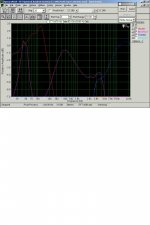
Looks like you have a mid with rising response, so the higher frequencies are electrically rolled off. There may also be a notch around 2.2K for a resonance peak.
You now need to check the response with a measurement mic, as Bill suggested, to see how these electrical slopes correspond to driver slopes.
You now need to check the response with a measurement mic, as Bill suggested, to see how these electrical slopes correspond to driver slopes.
Steve,
I'm not sure why you're in the Post Processing mode looking at a wav file. You should be able to capture excellent curves in the realtime mode. Anyway, try expanding the vertical scale so you can see much more of the overall curve. You can also set FFT greater than 4096 which will give more resolution in the lower frequencies. You can let it average continuously if you want.
Cheers,
Davey.
- Status
- This old topic is closed. If you want to reopen this topic, contact a moderator using the "Report Post" button.
- Home
- Loudspeakers
- Multi-Way
- reverse engineering a crossover?