Hi,
I'm measuring with an ECM8000 mic and a UB802 mixer used as a preamp. Speaker Workshop on my laptop, using the line out and mic in of the laptop (no line in, so I can't get a reference channel). I'd really appreciate it if someone could help me figure out what I'm seeing.
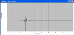
First, this is the impulse response with the output looped to the input. How bad is this? Should I get a USB soundcard? I don't know if the ringing before the impule is going to be a problem, especially since SW will see it in the mic signal and won't be able to correct it since there's no reference channel.
I'm measuring with an ECM8000 mic and a UB802 mixer used as a preamp. Speaker Workshop on my laptop, using the line out and mic in of the laptop (no line in, so I can't get a reference channel). I'd really appreciate it if someone could help me figure out what I'm seeing.
First, this is the impulse response with the output looped to the input. How bad is this? Should I get a USB soundcard? I don't know if the ringing before the impule is going to be a problem, especially since SW will see it in the mic signal and won't be able to correct it since there's no reference channel.
Attachments
Then we go on to the acoustic measurements. The speakers:
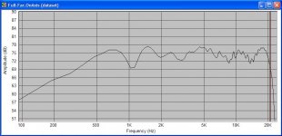
Fountek JP-3.0 and Audax PR170M0 on an open baffle, Eminence Beta 12CX in a sealed enclosure. The upper baffle has wings on the sides, the drivers are offset about 1/2" from the center. The speaker was pulled out into the middle of the room and the mic was about 5' away for these measurements. First, the gated on-axis measurement. There's a big dip at 1kHz and peak at 1.5kHz. I figured these were due to dipole cancellation/reinforcement. But then I tried a different test (next post).
An externally hosted image should be here but it was not working when we last tested it.
Fountek JP-3.0 and Audax PR170M0 on an open baffle, Eminence Beta 12CX in a sealed enclosure. The upper baffle has wings on the sides, the drivers are offset about 1/2" from the center. The speaker was pulled out into the middle of the room and the mic was about 5' away for these measurements. First, the gated on-axis measurement. There's a big dip at 1kHz and peak at 1.5kHz. I figured these were due to dipole cancellation/reinforcement. But then I tried a different test (next post).
Attachments
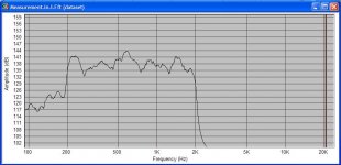
I ran a sine wave sweep from 200Hz to 2kHz and then ran an FFT on it. This is that data, smoothed to 1/6 octave. The XO between the woofer and midrange is an active 4th order Linkwitz-Riley at 500Hz. This tells me that my wooferlevel is adjusted correctly, and moreover, I don't see the peak/dip of the previous graph showing up to quite the same extent.
If I run a sweep test all the way out to 2kHz, it shows a steadily drooping top end.
So my questions are basically, what does all this mean, and which one do I trust? I'm guesing I should trust the gated MLS test for the top end. But I'm not sure which result I should go with for the 500Hz region. Should I try a notch filter on the midrange?
Any ideas and/or advice would be very helpful.
Thanks,
Saurav
Attachments
Hi Saurav,
firstly you could try doing a calculate freq response on your impulse measurement from your sound card and see how it looks, if it looks flat it's probably ok, if it doesn't then maybe it isn't.
for a better test of your soundcard dowload rmaa http://audio.rightmark.org/index_new.shtml though I'm not too sure about using the mic input instead of a line in. might overload it.
on the measurements, you probably need to do some nearfield measurements for freq under 200Hz... (though you might want to check that as it could be dependent on woofer diameter, can't remember off the top of my head.
I'm not going to try and interpret your data") but you might want to check things like the length of a wavelength at your various dip freq's and see if they correspond with any baffle dimentions.
but you might want to check things like the length of a wavelength at your various dip freq's and see if they correspond with any baffle dimentions.
Only other thing I'd ask is did you do an impulse test before the onaxis response tests, and adjust the gate time to keep out the room reflections?
Tony.
Tony.
firstly you could try doing a calculate freq response on your impulse measurement from your sound card and see how it looks, if it looks flat it's probably ok, if it doesn't then maybe it isn't.
for a better test of your soundcard dowload rmaa http://audio.rightmark.org/index_new.shtml though I'm not too sure about using the mic input instead of a line in. might overload it.
on the measurements, you probably need to do some nearfield measurements for freq under 200Hz... (though you might want to check that as it could be dependent on woofer diameter, can't remember off the top of my head.
I'm not going to try and interpret your data
but you might want to check things like the length of a wavelength at your various dip freq's and see if they correspond with any baffle dimentions. Only other thing I'd ask is did you do an impulse test before the onaxis response tests, and adjust the gate time to keep out the room reflections?
Tony.
Tony.
hmmmm just realised that rmaa requires both channels on input, so that won't work with using the mic input.
Also realised you said your mic was about 5 feet away. I think that this is too far, should probably be no more than about 3 feet away for gated measurements if I recall rightly. You could measure at 5 feet farfield if you want to get an idea of your in room response.
Tony.
Also realised you said your mic was about 5 feet away. I think that this is too far, should probably be no more than about 3 feet away for gated measurements if I recall rightly. You could measure at 5 feet farfield if you want to get an idea of your in room response.
Tony.
Hi Tony,
Thanks for the help. Yes, I did set the gating window based on an impulse test. I noticed something after I posted the question - the dip gets deeper if I increase the gating window and re-run the same measurement, and gets smaller if I reduce the window. So I'm wondering if that's a reflection I'm picking up. I tried measurements at 3' too, yesterday I rearranged my speakers to try a measurement from further away to see if it made any difference. I've tried RMAA, it gets pretty confused since it doesn't see any signal on one of the inputs. Some day I'll get a USB soundcard and then I can use all this software the way they were meant to be used
Thanks for the help. Yes, I did set the gating window based on an impulse test. I noticed something after I posted the question - the dip gets deeper if I increase the gating window and re-run the same measurement, and gets smaller if I reduce the window. So I'm wondering if that's a reflection I'm picking up. I tried measurements at 3' too, yesterday I rearranged my speakers to try a measurement from further away to see if it made any difference. I've tried RMAA, it gets pretty confused since it doesn't see any signal on one of the inputs. Some day I'll get a USB soundcard and then I can use all this software the way they were meant to be used
Farfield measurements are performed to get accurate data from drivers in the cabinet. Performing near field pretty much removes any affects of cabinet diffraction but also introduces issues with wave cancellation becase the microphone is too close to the drivers cone. When measuring at low frequencies these are not apparent because the wavelengths involved are much to large to cause any ill effects with a microphone close to the driver cone.
But in a farfield situation, unless you have an anechoic situation, you include diffraction effects from the baffle and drivers mounted on the baffle, but you also introduce room reflections. Because of this you need to set a window for measurement of less then the time it takes the wave from the loudspeaker to reach the closest reflective surface and reach the microphone, otherwise you bump into problems. The response usually becomes wavey or you get peaks and troughs in it if the time is set too high.
Now when you create this time period it also limits the lower measuring. This is because (I think) the window of time is not long enough to allow the wavelenth of a lower frequency to pass through compression and rarefaction so the lower frequencies measured are not accurate.
Increase the time window and you can measure down lower but also introduce wall reflections from a far field point of view. So whats normally done is a near field measurement is taken for the lower range and a farfield is taken for the upper range (if its a tweeter a far field is sufficient on its own), then the two are spliced together.
The farfield measurement usually reaches down as low as it can go depending on the room it is measured in. I usually have to splice at about 400-500hz.
Everything you said is essentially correct. The only part I want to clarify is below:
The shorter time period lowers the resolution of the fft. For example if you set up your time window to measure down to 300hz. Then you get valid data every 300 hz. i.e. 300, 600, 900, 1200 etc. As you can see you end up with only 3 good data points below 1khz.
This is why I prefer to use a swept sine measurement for low frequency data between about 300 hz to 1khz or so. With Clio I can set a delay to remove the time of flight (simular to gating a MLS measurement). This allows me to keep reflections out of the swept sine measurement but it dose not effect the resolution.
I use nearfield below 300hz and model the baffle step.
Russ
5th element said:Now when you create this time period it also limits the lower measuring. This is because (I think) the window of time is not long enough to allow the wavelenth of a lower frequency to pass through compression and rarefaction so the lower frequencies measured are not accurate.
The shorter time period lowers the resolution of the fft. For example if you set up your time window to measure down to 300hz. Then you get valid data every 300 hz. i.e. 300, 600, 900, 1200 etc. As you can see you end up with only 3 good data points below 1khz.
This is why I prefer to use a swept sine measurement for low frequency data between about 300 hz to 1khz or so. With Clio I can set a delay to remove the time of flight (simular to gating a MLS measurement). This allows me to keep reflections out of the swept sine measurement but it dose not effect the resolution.
I use nearfield below 300hz and model the baffle step.
Russ
Saurav said:First, this is the impulse response with the output looped to the input. How bad is this? Should I get a USB soundcard? I don't know if the ringing before the impule is going to be a problem, especially since SW will see it in the mic signal and won't be able to correct it since there's no reference channel.
The impulse should be going positive. This happened because the mic preamp probably inverts the signal. All you need to do is reverse the signal going to the drivers by swapping the speaker cable i.e. plus to minus instead of plus to plus. This is a very common.
Russ
I've stayed away from nearfield so far, because I have an open baffle from 500Hz up, and I'm not sure I'll pick up accurate readings if I get too close to the baffle - wouldn't that give me just the front wave?
As I said, I've tried sine wave sweeps, and they give me fairly different-looking results from the MLS tests, especially in the 500Hz region which is where I XO from the midrange to the woofer. So what you're basically saying is that I should trust the sweep tests for that frequency range and not the MLS.
I noticed the MSL resolution go down as I reduced the window. The graph became very smooth
Last night I also downloaded a free RTA program. It only had 1 octave resolution (really fat bars), but that helped me in adjusting woofer-midrange level. Setting it to where the MLS looked good resulted in the woofer level being set too low (to my ears). Setting it based on the RTA reading sounded much better balanced.
The negative impulse is with a loopback cable. When I measure my speakers, they go positive. So I guess my preamp+amp also inverts polarity. Will the polarity affect the measurements?
Also, could you please explain the delay on the swept sine wave test? I want to see if I can do something similar with Speaker Workshop.
And finally, is there any software that can take an MLS or impulse test's data and generate the step response? I'd really like to see my speaker's step response, but SW can't generate that.
Saurav said:I've stayed away from nearfield so far, because I have an open baffle from 500Hz up, and I'm not sure I'll pick up accurate readings if I get too close to the baffle - wouldn't that give me just the front wave?
Yes, dipoles are a bit trickier to measure. what I described is my general method of measuring drivers in a sealed box. I don't have any experience measuring a dipole. What frequency are you crossing over to the woofer?
As I said, I've tried sine wave sweeps, and they give me fairly different-looking results from the MLS tests, especially in the 500Hz region which is where I XO from the midrange to the woofer. So what you're basically saying is that I should trust the sweep tests for that frequency range and not the MLS.
[\B]
In general, yes.
Also, could you please explain the delay on the swept sine wave test? I want to see if I can do something similar with Speaker Workshop.
[\B]
First let me clarify. Clio does a stepped sine and not a swept sine. That means it steps from one discrete frequency to the next.
Anyway, what it allows you to do in the setup is specify a "Delay Time" and an "On Time". The Delay allows you to remove the time of flight and the On time tells it how long to sample.
For example: If the flight time is 3ms and the first reflection is at 7ms, you would set Delay for about 2.99ms and the On time to 6.99ms.
There is also an Auto mode that will set the times for you automatically.
Russ
What frequency are you crossing over to the woofer?
500Hz.
First let me clarify. Clio does a stepped sine and not a swept sine. That means it steps from one discrete frequency to the next.
OK, I can get SW to do that. Why is a stepped sine test better than a swept sine test? And thanks for the explanation. I'll have to look for settings that are similar to the delay and on time. I'm not sure if I've seen anything like that.
Saurav said:
500Hz.
OK, I can get SW to do that. Why is a stepped sine test better than a swept sine test? And thanks for the explanation. I'll have to look for settings that are similar to the delay and on time. I'm not sure if I've seen anything like that.
Stepped sine is not better, I just wanted to clarify what Clio does.
Russ
- Status
- This old topic is closed. If you want to reopen this topic, contact a moderator using the "Report Post" button.
- Home
- Loudspeakers
- Multi-Way
- Need help understanding these measurements