Chipco issued the challenge so here it is:
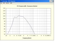
A 2 meter tall array of 16 NSB drivers as a front loaded horn. Bill said it couldn't be done but I believe the combined Sd of 800cm is what does the trick. HornResp is showing me 102-105db/w/m from 40hz to 200hz with 8 ohm wiring. That should match well with the array since I don't think the horn will get array projection. If the room makes it too bass heavy just add the optional final flare and move it out of the corner.
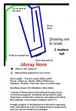
Using a corner to form the final horn segment, it's only 16.5cm (6.5") wide at the front, 23cm (9") in the back and only 50cm (20") deep....... but 2 meters (6.5ft) tall. It does need to go in a corner, but using side wall placement will only cost you about 3db between 40 & 80hz. I stayed middle of the road with the rules of thumb for horns and trying different driver and construction variances got the same result. It should work with just about any 4" driver and be forgiving to minor construction variances. Changing the angle of the cab to the side wall has little effect so placement can be used to fine tune the horn's upper cutoff and to suit your listening position.
3 sheets of 3/4" or 18mm ply plus $16 worth of NSB's and whatever you are going to do about the tweets will get you from 40hz on up. It still has over 92db/w/m at 30hz, so with room gain it should have nice extension.
Construction will be pretty simple. Just 7 rectangular pieces each 2 meters long, plus top and bottom caps gives you the basic construction. 27 narrow rib divider/braces would be ideal and might be tedious. I believe rounded corners are unnecessary due to the low 200hz upper cutoff, but if you wanted to, simple 3/4" corner moulding would be sufficient for most of the corners due to the narrow widths of the passages.
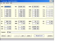
I'll attach the Hornresp parameters and response graph if someone tells me how.
If I've lost my mind and completely missed the boat somehow, will someone please throw me a rope.
Below is a drawing done in paint. Sorry I don't have any kind of construction drawing program, so it's not to scale.
A 2 meter tall array of 16 NSB drivers as a front loaded horn. Bill said it couldn't be done but I believe the combined Sd of 800cm is what does the trick. HornResp is showing me 102-105db/w/m from 40hz to 200hz with 8 ohm wiring. That should match well with the array since I don't think the horn will get array projection. If the room makes it too bass heavy just add the optional final flare and move it out of the corner.
Using a corner to form the final horn segment, it's only 16.5cm (6.5") wide at the front, 23cm (9") in the back and only 50cm (20") deep....... but 2 meters (6.5ft) tall. It does need to go in a corner, but using side wall placement will only cost you about 3db between 40 & 80hz. I stayed middle of the road with the rules of thumb for horns and trying different driver and construction variances got the same result. It should work with just about any 4" driver and be forgiving to minor construction variances. Changing the angle of the cab to the side wall has little effect so placement can be used to fine tune the horn's upper cutoff and to suit your listening position.
3 sheets of 3/4" or 18mm ply plus $16 worth of NSB's and whatever you are going to do about the tweets will get you from 40hz on up. It still has over 92db/w/m at 30hz, so with room gain it should have nice extension.
Construction will be pretty simple. Just 7 rectangular pieces each 2 meters long, plus top and bottom caps gives you the basic construction. 27 narrow rib divider/braces would be ideal and might be tedious. I believe rounded corners are unnecessary due to the low 200hz upper cutoff, but if you wanted to, simple 3/4" corner moulding would be sufficient for most of the corners due to the narrow widths of the passages.
I'll attach the Hornresp parameters and response graph if someone tells me how.
If I've lost my mind and completely missed the boat somehow, will someone please throw me a rope.
Below is a drawing done in paint. Sorry I don't have any kind of construction drawing program, so it's not to scale.
Attachments
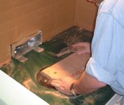
Hi, I don't know much about horn design but I can advise on ribs. It looks as though each rib could be made up of two or more parts so make a set of templates out of thin hard stuff like masonite and cut out copies on the router table with a template bit.
Attachments
Actually I have the dimensions all calculated for the ribs to be cut from the same plywood. Their all just long skinny triangles easy to rip with the table saw. Those for the 1st and 2nd segments would probably be best cut as one piece, so I don't have open space at the turn. Again easy with the table saw. I need so many because the throat starts as only 324sq cm which with 11 dividers is 12 channels with an 18mm width (easy spacing with scraps) by 150mm high. That's an 8/1 ratio and I think much larger than that is problematic. The termination of segment 2 is a total cross sectional area of 980 cm sq comprised of 12 150mm high channels a hair over 54mm wide, a good ratio. Pairs of channels coming out of segment 2 will flow into single channels using the 5 ribs in section 3. They'll start at 318mm by 55mm, ratio of less than 6/1 and terminate at less than 4/1. The final segment should probably be channeled too, but we'll see how it sounds without it.
With all those effective braces, it should be as solid as a rock. There's no dead spaces to waste volume and with the back not closed, some fudging at the end will be easy. The 2 side panels will go on last, so if something is off a little at the end it will make zero difference unlike a typical box.
I really got lucky how everything just flowed together perfectly from what I had pictured in my head. Once I got the horn length range down to a single wavelength at 200hz, the response gelled in the models almost instantly. At first I was thinking that I needed a much longer horn, but it was unnecessary due to the height of the cab.
Just have to set aside a day to build them. I already have a pair of 12 driver 7" wide hardwood baffles I can use, so no holes to cut, which makes 1 long day realistic. 12 of the B/K 4"ers I have have a +/- 2db from 42-200hz with the same dimension cab, so it's worth a shot.
Chipco issued the challenge
I'm not smart enough at this stuff to challenge anything! Looks like a GREAT project!
Chipco,
Can't live in these. It's only about 14" wide and 20" deep with the optional final segment built on, so it takes up less real estate than a typical floor plant. Using the corner and wall as the final segment, the cab is only 6.5" wide (9" at the back) by 20" deep.
You can sell the wife on the fact that it's smaller than you have now.
I've been thinking that with all that bracing, 1/2" ply will be fine which will cut an inch off of those dimensions. You'll barely be able to fit the drivers.
Probably a strip of thick vinyl or something similar would be a good way to attach it to the wall for stability and to seal the final bend, while leaving the angle somewhat adjustable.
To get down to 40hz, you need the 16 drivers. Whatever the layout, you have to retain the horn length and cross sectional areas through that length. Essentially the volume has to remain the same and if you cut it in half, the cab width would need to double and the distance from the wall would need to double. It would be 40" tall and require approximately 2ft by 2ft of floor space in the corner, since the mouth would need to be 13-15" wide. Still not bad considering $16 of drivers and sensitivity of about 100 from 40hz on up. Each would take less than a sheet of 3/4" ply. You'd give up line array dispersion except in the higher frequencies, so that might affect tonal balance. Without the array affect the 16 drivers won't keep up with the horn, so you'd have to also have to EQ the bass down some.
A lot less divider/braces would be required. Just 3 in the 1st horn segment and 1 in the 2nd and 3rd segments should be sufficient for keeping the channel width/hieght ratio low enough, but I'd go with 5 and 2 to minimize panel resonances.
A lot less divider/braces would be required. Just 3 in the 1st horn segment and 1 in the 2nd and 3rd segments should be sufficient for keeping the channel width/hieght ratio low enough, but I'd go with 5 and 2 to minimize panel resonances.
To get down to 40hz, you need the 16 drivers.
No, no, no... I am currently running a WAF credit acount.
I'm talking about 32 drivers per side. Two rows of 16.
What's the tweeter selection? Pyle's?
chipco3434 said:
No, no, no... I am currently running a WAF credit acount.
I'm talking about 32 drivers per side. Two rows of 16.
What's the tweeter selection? Pyle's?
Yes, I plan to use the pyle tweet because I know it works and I already have a pair not in use.
Double the drivers means double the throat area needed and that doubling extends through the entire horn. Essentially 50%-100% increase in width gets you no more extension, but a very flat response between 40 and 200, plus a slight efficiency gain.
You could redesign the whole thing and get down to 35hz, maybe even 30hz, but you need a much much bigger cab. It was like me trying to get below 40hz with 16 drivers and it just wasn't going to happen and still get a smooth response.
I tried it and 35hz looks ok. It takes about double width and probably 6" added depth. The horn is longer and gives you a 160hz cutoff and length which might work well with the driver's response. But 32 more holes to cut and drivers to wire for an extra 5hz of extension doesn't make sense to me. Plus a 120% increase in cab size and detriment to horizontal dispersion of having 2 line arrays side by side are just 2 more strikes against 32 per side. You'll have to figure out the folds yourself.
Back to the drawing board.
Don't cut any wood yet. The experts were supposed to catch a major faux pas. A rear horn is supposed to have a horn length equal to an ODD NUMBER OF 1/2 WAVELENGTHS OF THE UPPER HORN CUTOFF FREQUENCY. As it is now, the horn output would be directly out of phase with the front of the drivers at the crossover point. This would cause cancellation and a big dip in response at 200hz.
Back to the drawing board. I should have know it was too good to be true.
mike.e said:I replied to you on decware
Seal the back chamber to prevent 1/2wave cancellations.I dont know how vocals would sound coming beside the walls
Mike,
First, that's with the 49 cent pioneers, so it's $16 of drivers plus shipping total for 2 speakers. Add 2 $20 super tweets, some kind of xover due to the 7k peak on the cheap pioneers, an Lpad for the tweet, and 3 sheets of 12mm plywood. At a listening distance of 3-4 meters, for about $100 a pair plus work, you end up with a pair of speakers that's equal to a point source speaker with sensitivity of about 103db/1w/1m from 40-20khz , impedance of whatever you choose, and uses only a 24"x24" corner, but is 6.5ft tall.
I can't seal the back chamber because it's a rear horn. I got the upper cutoff cancellation just about licked, but I need to choose a cutoff frequency to finalize the layout. 120hz matches the -3db of the driver in a sealed box, but gives me a 3db dip in response centered at 50hz. Should I even worry about that dip?
Since it's a corner horn everything comes from the corners, but that should work great with the big tall image presented by an array.
The 2nd harmonic distortion part I don't understand. Is there a way estimate that? Maybe that's the hole in the whole idea of squeezing 40hz out of 16 drivers that have an Fs of 105hz.
You wont hear -3db unless you listen,in an anechoic room without room modes
You really cant estimate distortion.You could measure it. I guess with the combined area of a 15" the drivers wont be moving far at all
The horn will drop the Fs down due to the mass of air in the horn.
operating drivers below Fs is not a good idea,i only do it on my 2226 because it has SFG and shorting ring so distortions still quite low.
mike.e said:operating drivers below Fs is not a good idea.....
I've read in more than one place that the old time experts said that rear horns need drivers with an Fs higher than the low end cutoff.
Also, this isn't for high power, high output. I doubt that each driver will ever see even close to 1 watt. At 1/2 watt for each driver, 8 for the array, it will be at about 107db, which at a 4 meter listening distance will be the same as 113db from a point source due to the line array effect. Hopefully the low power operation will keep distortion at bay even though it's operating so far below Fs.
Re: Back to the drawing board.
GM
'Supposed to'?! I was in the process of explaining why Bill is right, answering your other Qs, and giving a bit of insight into the finer points of BLH design until I read this......johninCR said:The experts were supposed to catch a major faux pas.
GM
- Status
- This old topic is closed. If you want to reopen this topic, contact a moderator using the "Report Post" button.
- Home
- Loudspeakers
- Multi-Way
- Line Array Corner Horn for any 4" driver