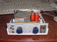
I needed a jig, I needed to practice soldering, I needed to review my ability to read electronics schematics, and I needed to begin working on my website. Besides getting the diodes turned around on the first try, and besides having to substitute some resistance, it has been a great success. What a nice design! Here are the pics:
Special thanks to Eric Wallin for providing the plans online for anyone to use.
Dave
PS--That's a box for a PCI card. Very sturdy.
Special thanks to Eric Wallin for providing the plans online for anyone to use.
An externally hosted image should be here but it was not working when we last tested it.
An externally hosted image should be here but it was not working when we last tested it.
Dave
PS--That's a box for a PCI card. Very sturdy.
Netlist said:Me?
No, it would cost you a fortune and I would spoil all the fun you
would have building it.
/Hugo")
heh... ive already tried building one. 3 trips to radio shack for $40 in parts. Now all I have is various & sundry fried, soldered and half-soldered electronic parts kicking about. The whole experience was NOT my idea of fun.
how much of a fortune are you talking?
Re: OK I'll bite...
Do a web search for speaker workshop.
Stocker said:And this does...?
Do a web search for speaker workshop.
Re: Re: OK I'll bite...
See, I thought about trying to explain Jig II, but it, in itself, is a complicated thingy that goes with Speaker Workshop, which is also a complicated thingy of the software sort (free, too!). In short, put both together, and you can measure anything to your heart's delight with relative accuracy.
Right now I'm suffering through the calibration phase. My DMM says the Jig works, but my soundcard is pro-sumer style soundcard, and the resistance and output levels are somewhat different than defaults in SW. It's real pain, but there must be some gain...
Dave
Ron E said:
Do a web search for speaker workshop.
See, I thought about trying to explain Jig II, but it, in itself, is a complicated thingy that goes with Speaker Workshop, which is also a complicated thingy of the software sort (free, too!). In short, put both together, and you can measure anything to your heart's delight with relative accuracy.
Right now I'm suffering through the calibration phase. My DMM says the Jig works, but my soundcard is pro-sumer style soundcard, and the resistance and output levels are somewhat different than defaults in SW. It's real pain, but there must be some gain...
Dave
Does anyone know the answer to this one? Eric Wallin has a site that walks you through the calibration process, and I'm thoroughly confused by the impedance calibration.
What is the "value of your 16ohm calibration resistor" if it's not 16? I don't get it. And the numbers I'm getting are whacked out. Big negatives and whatnot.
Dave
PS--here's the link
http://www.gti.net/wallin/audio/SW/comp_meas/comp_meas.html
If you know the input impedance of your soundcard, enter this here. If you don't know, use the defaults recommended in the SW help. After that, press the upper Test... button and then press the Next > button on the dialog that pops up. Enter the value of your 16 ohm calibration resistor and press the Next> button. Wait until the recording has stopped, then flick SW1 to the down position. Enter the value of your 4 ohm calibration resistor and press the Next > button. Now take a look at the ending dialog:
What is the "value of your 16ohm calibration resistor" if it's not 16? I don't get it. And the numbers I'm getting are whacked out. Big negatives and whatnot.
Dave
PS--here's the link
http://www.gti.net/wallin/audio/SW/comp_meas/comp_meas.html
What is the "value of your 16ohm calibration resistor" if it's not 16?
He means enter 15.8ohm, if that's what you measured. Just enter 16 ohms if you used 1% resistors - measuring with a DMM would give an error greater than 1% with such low value resistors.
And the numbers I'm getting are whacked out.
Turn on the VU Meter (I think it's under the View menu). You should now have a box in the bottom left corner showing what the signal sizes are. What figures are you seeing when doing the calibration? If RIGHT is larger than LEFT then try reversing the left and right line-in connections to the soundcard. There's an option to do this in the options/preferences/measurements menus, labelled "reverse channels".
Jay Butterman has produced an excellent, detailed manual (site is currently down):
http://www.audiodiycentral.com/
Nice one,
David.
Diy can be hard indeed but keep practicing. Try to find someone who can actually show you how to solder. This will take away a lot of frustration.Kittle said:
Now all I have is various & sundry fried, soldered and half-soldered electronic parts kicking about. The whole experience was NOT my idea of fun.
how much of a fortune are you talking?
Sorry, I'm really not going to build it for you, no matter what money you offer me
Yes, I remember having problems with that too.kneadle said:
What is the "value of your 16ohm calibration resistor" if it's not 16? I don't get it.
I guess I simply entered 16 and 4. But it's about two years ago.
/Hugo
Netlist said:
Diy can be hard indeed but keep practicing. Try to find someone who can actually show you how to solder. This will take away a lot of frustration.
Sorry, I'm really not going to build it for you, no matter what money you offer me
Yes, I remember having problems with that too.
I guess I simply entered 16 and 4. But it's about two years ago.
/Hugo
The vlaue of your calibration resistors are what you put there. Simple as that. If you used 2 pieces of 8R2 in series for the 16 Ohm and 2 pieces of 8R2 in parallell for the 4 Ohm when the values are 16.4 and 4.1 repectively....
daatkins said:
He means enter 15.8ohm, if that's what you measured. Just enter 16 ohms if you used 1% resistors - measuring with a DMM would give an error greater than 1% with such low value resistors.
Turn on the VU Meter (I think it's under the View menu). You should now have a box in the bottom left corner showing what the signal sizes are. What figures are you seeing when doing the calibration? If RIGHT is larger than LEFT then try reversing the left and right line-in connections to the soundcard. There's an option to do this in the options/preferences/measurements menus, labelled "reverse channels".
Jay Butterman has produced an excellent, detailed manual (site is currently down):
http://www.audiodiycentral.com/
Nice one,
David.
UrSv said:
The vlaue of your calibration resistors are what you put there. Simple as that. If you used 2 pieces of 8R2 in series for the 16 Ohm and 2 pieces of 8R2 in parallell for the 4 Ohm when the values are 16.4 and 4.1 repectively....
I did find the detailed manual, and I did find Claudio Negro's homepage. So combined with Eric Wallin's instructions, I finally figured it all out.
One of the most confusing things is that the switch positions put the 16 or 4 ohm resistor to binding post 3 and 4, and Eric has you put a short between the posts. The other manuals and sites don't have that, and everything came out fine.
As my understanding of circuitry is not terribly advanced, I don't understand why the designer of Jig II himself wants a short there.
Another difficulty is the fact that he uses--correctly--low-end consumer level soundcards in his analysis. I have a pretty nice professional recording sound card. The signal levels are wildly divergent.
The alternate manuals showed me how to increase the TIME, not the power (which I tried), so that Speaker Workshop was able to make accurate measurements.
So, in summary, there were two problems: 1) a confusing short across the calibrating loads; 2) Speaker Workshop needing more time with currently produced and higher end soundcards.
Dave
Good to read your problem is sorted. When Speaker Workshop is up and running, it really is a great piece of software!
Indeed. I found the number of switches quite confusing so condensed them onto two rotary switches. My jig also includes a Gainclone-type power amp and a mic preamp all in one box.
Nice one,
David.
One of the most confusing things is that the switch positions put the 16 or 4 ohm resistor to binding post 3 and 4, and Eric has you put a short between the posts.
Indeed. I found the number of switches quite confusing so condensed them onto two rotary switches. My jig also includes a Gainclone-type power amp and a mic preamp all in one box.
Nice one,
David.
Attachments
daatkins said:Good to read your problem is sorted. When Speaker Workshop is up and running, it really is a great piece of software!
Indeed. I found the number of switches quite confusing so condensed them onto two rotary switches. My jig also includes a Gainclone-type power amp and a mic preamp all in one box.
Nice one,
David.
Wow, that's exactly what I was going to do!
Dave
It is unclear why Eric had the short in place as it will throw off the results. I suspect that it may have been that his first jig required it but Jig II does not.
I am glad that you got the set up working. Enjoy. It is powerful and accurate software for the price. There are a few features that would be nice to have but I doubt we will see them with this as Mark Zachmann is now tied up with Eagleware, a software company, and appears to have dropped out of the picture. Thanks to him, though, for providing the software to begin with.
Jay Butterman
Re: How big an amp?
You're going to be sucked into Gainclone amp-building as I have only recently. Run!
Seriously, check the chip amp section of DIYaudio forums.
The way I figure it, I'll have a whole DIY testing station in my basement workshop, dedicated to building and producing amps, preamps and crazy TL speakers. A centralized reference amp, reference speakers, and jig will be the cat's meow.
And to answer your question. Quite small. Quite small. Unbelievably small. I don't know about wattage for testing, but Jig II and Speaker Workshop are designed to work with amps as well as passively (or something like that).
Dave
bg40403 said:daatkins said:
"My jig also includes a Gainclone-type power amp and a mic preamp all in one box."
It sounds like such a good idea to put it all in one box. How big should the amp be? What wattage is adequate for testing?
You're going to be sucked into Gainclone amp-building as I have only recently. Run!
Seriously, check the chip amp section of DIYaudio forums.
The way I figure it, I'll have a whole DIY testing station in my basement workshop, dedicated to building and producing amps, preamps and crazy TL speakers. A centralized reference amp, reference speakers, and jig will be the cat's meow.
And to answer your question. Quite small. Quite small. Unbelievably small. I don't know about wattage for testing, but Jig II and Speaker Workshop are designed to work with amps as well as passively (or something like that).
Dave
I thought so
Cool, You are the 1st one I've posed that question to. I've got the jig parted out, the brass for the mike wand in hand, the calibrated electret located. Several chips available...snazzlefratchit....the Yankees just got their first run...but only one Ha ha ha
Buiding speakers has been so cool already...but the future's so bright I just gotta wear shades!
- Status
- This old topic is closed. If you want to reopen this topic, contact a moderator using the "Report Post" button.
- Home
- Loudspeakers
- Multi-Way
- I built Jig II by Eric Wallin