I've used cheap electret mic inserts to measure frequency response. They respond much too well to air currents, draughts and the like, so they have a good response down to fractions of a Hz. Even cheap ones. It's at high frequencies that cheap ones suffer, and maybe at high spls.
Mount the mic in front of the speaker, not inside the box. Change in pressure as cone moves in is not equal to change in pressure as cone moves out, so you will get 2nd harmonic distortion if you mount it inside the box.
The main problem I see is that you will get a power oscillator if you don't take care to minimise phase shifts. It's best to use a 'scope to monitor it. Use a pot at the output of the preamp, turn it up gradually, if it starts to oscillate turn it back down quickly. Reverse the polarity and try again. If it still oscillates, compensation might help.
Try it, I think some others on the forum have done it before.
I have tried circuits like this some 15 years ago. I also tried to do it with cheap electret mic's but they have a minor problem, sound pressure. The sound pressure at this close to a speaker becomes very high and these little mic's are not able to handle it. in other words, you are getting more distortion from this circuit than without.
It's better to use piezo electric elements directly glueed on to the woofer cone. This can give very good results.
One more thing. You will need a crossover for the speaker and the same crossover for the microphone signal. Otherwise the feedback from the microphone tries to correct the signal for a flat response, in other words, it tries to correct the crossover for the woofer back to lineair.
Hi Sjef,
Thanks for your comments. I was thinking about using a WM-61 with the 'Linkwitz' modification. This should minimize the distortion from the mic and make it capeble of high SPLs.. I have no idea how effective the mod is... It's a good point to keep in mind.
I don't understand you're remarks about the cross-over, could you explain?
About the crossover,
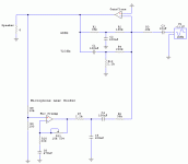
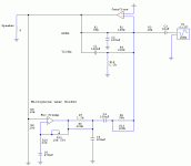
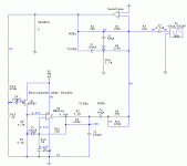
in your schematic you have a crossover in the feedbackloop of the chipamp. There is also a feedbackloop created by the microphone signal. This is a lineair feedback loop. With a feedbackloop you constantly compare the output signal with the input signal and try to compensate for errors within the limits of the feedbackcircuit. This circuit tries to make the output lineair again (within the capabilities of the feedbackloop offcoarse).
Put the crossover before the whole circuit or be sure that the feedbackloop has the same transferfunction as you want to be on the output.
Hi Sjef,
The feedback around the poweramplifier is a band-reject filter, Fc are 60Hz and 725Hz.. this band is filled in with the feedback from the mic, which has a bandpass filter with the same corner frequencies.. because it are 1st order filter, the sum is allmost perfect...There is the same amount of feedback
DC-60Hz : voltage feedback from the output
60-725Hz: acoustic feedback from the microphone
725- HF : voltage feedback from the output
Edit.. the woofer is used up to 2.4KHz and passively crossed to the tweerter with a 2nd order L-R passise crossover..
tschrama,
if you want to play around a little I would like to suggest optical feedback for the woofer cone. Like a simple infrared reflex detector.
That way you won't have any time lag in the feedback loop.
Like someone else here said, it is very easy for this thing to turn into a full-feathered power oscillator. Generally, systems with a time lag are VERY difficult to regulate with standard linear feedback systems.
And also, I would only expect this to work for a powered sub (<100 Hz). This would give the additional advantage of not exceeding Xmax and thus blown woofers. IIRC Yorkville did this (don't know if they used a pressure sensor or something else though) in their powered subs for the "True Blue" line of PA speakers.
Cheers
/Magnus
no problem Sjef!
Swedish Chef: yes indeed... I got a time delay, if only 50 to 100microseconds .. I have no way of simulating this and I am not capable of calculating the effects... but my instinct says it's imposible to apply feedback around a time delay... anyone has experience which such a thing?
What about if I glue the microphone on the speaker cone?
tschrama,
the problem with a time delay in a feedback system is that it drastically reduces the phase margin of the system. Therefore, you have to keep the bandwidth down to ensure stability. That is one of the reasons i dont expect a speaker feedback system to effectively be used much above say a few hundred Hz, apart from the problem of cone breakup distortion which can not be compensated for by a feedback loop.
The usual way to combat time delays is with a regulator structure called the "Otto Smith regulator". The only problem with this structure is that it contains a delay section which is pretty hard to implement with analog electronics but very easy with a digital system*...
So the easiest way would just be to reduce the bandwidth of the loop.
* Nowadays I pretty much hate everything digital. As a friend said "a digital circuit is simply an analog circuit that is broken".

/Magnus
the problem with a time delay in a feedback system is that it drastically reduces the phase margin of the system. Therefore, you have to keep the bandwidth down to ensure stability. That is one of the reasons i dont expect a speaker feedback system to effectively be used much above say a few hundred Hz, apart from the problem of cone breakup distortion which can not be compensated for by a feedback loop.
The usual way to combat time delays is with a regulator structure called the "Otto Smith regulator". The only problem with this structure is that it contains a delay section which is pretty hard to implement with analog electronics but very easy with a digital system*...
So the easiest way would just be to reduce the bandwidth of the loop.
* Nowadays I pretty much hate everything digital. As a friend said "a digital circuit is simply an analog circuit that is broken".
/Magnus
the problem with a time delay in a feedback system is that it drastically reduces the phase margin of the system. Therefore, you have to keep the bandwidth down to ensure stability. That is one of the reasons i dont expect a speaker feedback system to effectively be used much above say a few hundred Hz
Is there a way to calculate the reduction of phase margin or the maximum practicle frequecy? Why do you think a few 100 Hz and not a few 10's or a few 1000' s ? I asume it is not just the 360 * mic distance/wavelength...
It would be difficult to calculate without any meaningful numbers to plug in to the equations. You would need to rig it up open-loop and measure it, then you would have some idea of its behaviour when you close the loop.
Excessive phase shifts can occur at both high and low frequencies. You are probably familiar with high frequency compensation, Cdom in power amps etc. Ask the tube guys about "motorboating" to hear about low frequency instability. I discussed this very briefly in this thread
hope this helps.
Excessive phase shifts can occur at both high and low frequencies. You are probably familiar with high frequency compensation, Cdom in power amps etc. Ask the tube guys about "motorboating" to hear about low frequency instability. I discussed this very briefly in this thread
hope this helps.
Is there a way to calculate the reduction of phase margin or the maximum practicle frequecy?
Yes, of course there is. But do you really want to do it? You can simulate the entire system in MATLAB if you want to spend a few hours of quality time. Assuming that you are quite familiar with linear algebra and Laplace transforms that is. In case you have not used MATLAB it is an extremely powerful tool for the engineer or scientist who knows what he/she is doing. But it's got a bit of a learning curve.
Doing like Johnny says is definitely the simplest path and the most likely to produce quick results. About the frequency range that was just my "gut feeling" based on experience with other systems and what I can remember others achieved in doing this. If you can make it work up to 1000 Hz, great! But just don't expect it to run that high.
What about if I glue the microphone on the speaker cone?
This is most likely going to produce SPL:s that far exceeds the range of the mic. But you can always try it. If I was going to have a shot at this I would definitely go for a direct motion measurement method of the speaker cone travel. But that is just me.
Cheers
/Magnus
Different idea
Hi,
I remember seeing a long time ago in a magazine called "Electronics World" a subwoofer that used a driver with two coils where one of the cils was driven by the amp and the other coil was used to provide feedback.
Presumably this would give a much more accurate indication of movement of the bit in the middle, if not the cone itself.
Arnie
- Status
- This old topic is closed. If you want to reopen this topic, contact a moderator using the "Report Post" button.
- Home
- Loudspeakers
- Multi-Way
- Microphone Feedback to correct Woofer


