Thanks all of you! Great info, great Link to that thread!
I am actually pretty familiar with MATLAB, but I haven't simulated anything like this with MATLAB before....
I the mean time I have read suggetions like: using current feedback to gain 90degrees of phase margin.. is that right?
Well, I think i'ts time to make that microphone first, examine it's SPL capabilities and the response curves/delays/phase etc...
Greetings,
Thijs
Another cone location measurement method (besides optical, capacitively/inductively) could be to mount small accelerometers on the cone. Either the classic piezoelectric type or the more recent MEMS type (like the Analog Devices ADXL series, great stuff BTW, I used them once for a basic inertial navigation system). Integrate the signal twice with simple opamp type integrators and voilá - you have the location!
Any offset will find its way through the double-integration though...
But then, you could always take the derivative of the music signal and apply feedback here... hmm just a thought, perhaps it's not a good idea...
Keep us informed when you have done the measurements!
Cheers
/Magnus
Any offset will find its way through the double-integration though...
But then, you could always take the derivative of the music signal and apply feedback here... hmm just a thought, perhaps it's not a good idea...
Keep us informed when you have done the measurements!
Cheers
/Magnus
Since I authored a patent (4,899,387) on a very similar
system, also using the Panasonic electret, I can speak from
some experience.
It works well enough, and you want to have the mic as close to
the center surface of the woofer as possible, but you'll still
find that you can only have limited bandwidth and a limited
amount of feedback. I centered mine at about 80 - 100 Hz
and began a single-pole rolloff above and below that range.
The amount of feedback that I could get away with was 6 to
10 dB while still retaining stability in any acoustic situation,
and of course your results will vary.
Keep in mind that the placement of the speaker - near the
floor, corner, or wall - affects the stability, so don't assume
stability in a given position based on performance in another.
In the seventies FunkTechnik published a diagram of Philips system in which a bass speaker was connected to an amplifier with correction unit. The unit was driven by a signal from the piezoelectric sensor glued to coil cone. Sensor signal was amplified by FET preamp placed in the vicinity.
Accelerometer Feedback.
I have found my copy of Wireless World September 1981 (after a long search). In this issue is a design by D. De Greef and J. Vandewege using Philips AD8067/WMFB4 20cm woofers. These woofers have built-in piezo transducers, and were used commercially by Philips in their own MFB designs many years ago.
It looks a bit dated, you can see how far technology has progressed in our use of chips and computer systems, but the results are what counts.
If anyone is interested in a copy of the article, send me an e-mail. I will scan it and send you a copy. Anyone following this thread will be interested for sure.
You got mail...
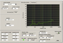
I just got a my LabView sound measurement system up and running and started to measure the microphone capsule. It looks like the WM-61 performs very close to the datasheet specs. I do measure a 3dB/oct rise in noise from about 2KHz... it's offtopic, but does anyone know what this could be?
Tommorow I gotta work, but 'll be back soon...
Thijs
I just got a my LabView sound measurement system
up and running and started to measure the microphone capsule. It looks like the WM-61 performs very close to the datasheet specs. I do measure a 3dB/oct rise in noise from about 2KHz... it's offtopic, but does anyone know what this could be?Tommorow I gotta work, but 'll be back soon...
Thijs
Hmm, thermal noise is spectrally flat well into the GHz range so that seems unlikely. Usually you see like a 3dB/oct rise in noise BELOW 1-10 kHz coz' of flicker noise (1/f-noise) so this is strange...
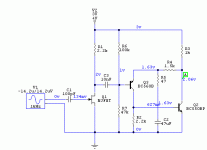
Could you post a schematic for the mic amp and pictures of the noise spectrum?
/Magnus
Could you post a schematic for the mic amp and pictures of the noise spectrum?
/Magnus
The preamp is something I got lying around... 2x1.5V battery, 2 transistor thingy, but it should be noiseless compared to the Mic..
The microphone capsule is pushed in a perfect matching hole, that I drilled in my wooden desk.. this attenuated evironment noise by atleast 10dB...
50 and 100Hz amplitudes are measurements artefacts.. I think the 15KHz is a no-antialiasing artefact...
I'll attach my octave analysis..
The microphone capsule is pushed in a perfect matching hole, that I drilled in my wooden desk.. this attenuated evironment noise by atleast 10dB...
50 and 100Hz amplitudes are measurements artefacts.. I think the 15KHz is a no-antialiasing artefact...
I'll attach my octave analysis..
The microphone MFB principle has also been used by Backes and Mueller at the beginnign of the eighties. I once pointed to the according patent; if anyone is willing to use the search feature he is free to do so.
The most interesting fact is that they glued the mic to the cone in order to have the least possible delay between sound generation and detection. They glued it to the junction between cone and dustcap and the aperture was facing sideways, so it wouldn't act as an acceleration detector at the same time.
Talking of acceleration detectors: An MFB principle that uses the sound-pressure as input signal should give better results than any acceleration-detector based MFB, as long as the quality of the pressure detector is good enough.
BTW: Did anyone have a look at the Meyer X-10 ?
http://www.meyersound.com/products/studioseries/x-10/pdfs/x-10_ds.pdf
Regards
Charles
tschrama,
I am used to a HP 3585A spectrum analyzer and HP 8753D network analyzer so the LabView output isn't exactly stunning...
But some conclusions could be made. Sure you have 50 Hz and 100 Hz mains injected noise. The peak at 15kHz is probably the noise generated by the flyback transformer in your computer monitor (electrically and acoustically).
The rise in noise with frequency could be due to resistive loading of the mic capsule. It's a bit early to draw any definitive conclusion since there are so many unknown factors in the measurement setup (like the performance of the A/D in the LabView card etc).
Great if you post info as the project progresses!
Cheers
/Magnus
- Status
- This old topic is closed. If you want to reopen this topic, contact a moderator using the "Report Post" button.
- Home
- Loudspeakers
- Multi-Way
- Microphone Feedback to correct Woofer