2 days ago I went to the local store an purchase some chip amps just to play in current amplification mode .
I builded a pair of GMs MLTL speakers with the JX92s (if you like take a look at the Quarter Wave site gallery )and going to test also a pair of MLTL with the Fostex FE206E.
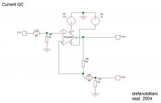
Reading the First Watt article by Nelson Pass , I decided to try the applications described. Actually, the tests are waiting for the FE206E to come although the enclosures are ready , by the way the JX92s gives a taste of what can be achieved following this different approach.
So the circuit attached is obtained following my tastes with the JX92 drivers in the GMs MLTL enclosure .
The circuit inspiration comes from the Elliot Sound pages variable impedance project.
As pointed out by Nelson I believe that the JX doesn't gain the full advantages from this kind of amplification and I will report back the results with the Fostex (they are more efficient) , but it is still worth trying and decide for yourself if it is good or not .
I like the results a lot anyway , and musically I prefear the current amp to the voltage one . They are just 2 different things")
The chip used is what I find in the local store and more chip are in count to try.They doesn't equal the class A for sure but they are cheap and very easy to build. More to the point, the speaker is included in the feedback loop - where in a class A current source it can be avoided .
So ... be prepared to enjoy
PS . The amp is dedicated to fullrange drivers .
I builded a pair of GMs MLTL speakers with the JX92s (if you like take a look at the Quarter Wave site gallery )and going to test also a pair of MLTL with the Fostex FE206E.
Reading the First Watt article by Nelson Pass , I decided to try the applications described. Actually, the tests are waiting for the FE206E to come although the enclosures are ready , by the way the JX92s gives a taste of what can be achieved following this different approach.
So the circuit attached is obtained following my tastes with the JX92 drivers in the GMs MLTL enclosure .
The circuit inspiration comes from the Elliot Sound pages variable impedance project.
As pointed out by Nelson I believe that the JX doesn't gain the full advantages from this kind of amplification and I will report back the results with the Fostex (they are more efficient) , but it is still worth trying and decide for yourself if it is good or not .
I like the results a lot anyway , and musically I prefear the current amp to the voltage one . They are just 2 different things
The chip used is what I find in the local store and more chip are in count to try.They doesn't equal the class A for sure but they are cheap and very easy to build. More to the point, the speaker is included in the feedback loop - where in a class A current source it can be avoided .
So ... be prepared to enjoy
PS . The amp is dedicated to fullrange drivers .
Attachments
Hi Stefano !
I must say,that I am very interested to try this current chip amp...I have some spare LM3875 and full range loudspeakers to drive them.
Well,I must say I am not really expert for electronic stuff.
I mean...I've build GC but here I could use some help.Rod Elliot article didn't helped me much...I just need plane and simple explanation;for example
...what happens if I change R5 or R3 ; how to calculate the gain of the amp.
Any help would be appreciated.
Regards,
Matjaz
P.S.
Should this thread be moved to chipamp forum?
I have read the article and I know this circuit is a mix mode amp
but Rod has put there 10k , 560ohm and 0.2ohm resistor and
Stefano has 22k , 220ohm and 1.4ohm if I recall it right.
So,if R1 is bigger , R2 should be smaller and R3 should be bigger
or is there any other rule to change resistors value if I want to
change output impedance and have gain of about 22.
I guess that R3 should be as small as possible to minimize the power lost.
Regards
There isn't an easy answer to how much "gain" this amp has. It varies with the loading. It's designed to be nearly load independant, so in other words it is capable of delivering 'x' amount of "power".
In low impedance loads, it puts out less gain than in high impedance loads because you need less voltage/current in order to drive lower impedances to the same power level.
No, if that were the case we could just omit R3 all together, 0 resistance or no resistor is as small as possible. R3 is the current gain resistor portion of the amp. It's value affects the Zo of the amp. The goal of this amp is to establish a particular output impedance. The reasons for this are varied. In Rod Elliots amplifier, he wants a Zo that resembles the Zo of a tube amp. In NPs article, he is using a different circuit to establish a Zo of 50ohms or so. So that it looks like a current mode amplifier or something like that.
I haven't really analyzed what stefano wants to do. Perhaps he is converting Rods schematic to 50 ohms output impedance? You could find out with a sim and a few calculations.
--
Danny
In low impedance loads, it puts out less gain than in high impedance loads because you need less voltage/current in order to drive lower impedances to the same power level.
I guess that R3 should be as small as possible to minimize the power lost.
No, if that were the case we could just omit R3 all together, 0 resistance or no resistor is as small as possible. R3 is the current gain resistor portion of the amp. It's value affects the Zo of the amp. The goal of this amp is to establish a particular output impedance. The reasons for this are varied. In Rod Elliots amplifier, he wants a Zo that resembles the Zo of a tube amp. In NPs article, he is using a different circuit to establish a Zo of 50ohms or so. So that it looks like a current mode amplifier or something like that.
I haven't really analyzed what stefano wants to do. Perhaps he is converting Rods schematic to 50 ohms output impedance? You could find out with a sim and a few calculations.
--
Danny
What I see is :Igla said:
So,if R1 is bigger , R2 should be smaller and R3 should be bigger
or is there any other rule to change resistors value if I want to
change output impedance and have gain of about 22.
Regards
R1 tends to be in parallel with the speaker if R2 tends to zero.
The speaker is not a pure resistor.
azira said:There isn't an easy answer to how much "gain" this amp has. It varies with the loading. It's designed to be nearly load independant, so in other words it is capable of delivering 'x' amount of "power".
In low impedance loads, it puts out less gain than in high impedance loads because you need less voltage/current in order to drive lower impedances to the same power level.
No, if that were the case we could just omit R3 all together, 0 resistance or no resistor is as small as possible. R3 is the current gain resistor portion of the amp. It's value affects the Zo of the amp. The goal of this amp is to establish a particular output impedance. The reasons for this are varied. In Rod Elliots amplifier, he wants a Zo that resembles the Zo of a tube amp. In NPs article, he is using a different circuit to establish a Zo of 50ohms or so. So that it looks like a current mode amplifier or something like that.
I haven't really analyzed what stefano wants to do. Perhaps he is converting Rods schematic to 50 ohms output impedance? You could find out with a sim and a few calculations.
--
Danny
Playing fiew ours listenig and changin the resistors values - with Jordans that are less than 90 db efficient - something told me that the differences are not so big in the end. There can be a sweet spot probably .
I have not analyzed my work too neither simulated .
I searced a more readable octaves contest in the bass guitar region. I guess a possible key here is experimenting with every set up and speaker and enclosure .
I do no count the gain as a possible problem playing with different speaker . Probably I am wrong . Again, I will let you know what happens with the Fostex Fe206e.
I am using the parallel eq network anyhow and wokrs well.
stefanobilliani said:
What I see is :
R1 tends to be in parallel with the speaker if R2 tends to zero.
The speaker is not a pure resistor.
Playing fiew ours listenig and changin the resistors values - with Jordans that are less than 90 db efficient - something told me that the differences are not so big in the end. There can be a sweet spot probably .
I have not analyzed my work too neither simulated .
I searced a more readable octaves contest in the bass guitar region. I guess a possible key here is experimenting with every set up and speaker and enclosure .
I do no count the gain as a possible problem playing with different speaker . Probably I am wrong . Again, I will let you know what happens with the Fostex Fe206e.
I am using the parallel eq network anyhow and wokrs well.
Sorry it seem a "telegraph road" reply .
Thanks for yours
Too late for an edit.
Yesterday evening I did some simulations of the circuit with
my CircuitMaker.
The results are not what I've been expecting...whatewer I did
(changing resistors) the output impedance of the circuit
stayed between 7 to 8 ohm from 20 to 20000Hz.
Changing R3 changed Zout just a bit...but bigger R3-smaller
gain.And changing R2 had no significant impact on Zout just on gain...smaller R2-bigger gain.
I was aiming for Zout to be 3 to 4 ohm and a gain of 20 to 22.
Perhaps it was just wrong simulation because did it with small
power op amps like ua 741 and similar.
azira said:
No, if that were the case we could just omit R3 all together, 0 resistance or no resistor is as small as possible.
--
Danny
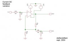
The opposite is of course use an R3 as high as say 8 ohm .
The price to pay - it comes to my eyes- it would be an high amount of feedback.
Not going to discover what are the effects of an high feedback amp once again , a way is to trow away some - feedbak - to ground.
This trick helps also to restore some gain even with R3 of 8 ohm.
BTW the variations are not critical at all. And despite of the losses in power the sound travel in a more overall natural direction.
And anyway with a 20W chip like the 2040 you will still stay safe even with the JX92 ;in fact the performance remains very well enjoiable it terms of dinamics also in this case .
There is a lot room for experimenting and satisfy your taste...
Attachments
Vix said:Hi
Did anyone try to use a TDA 7294 chip as a current source amp? If yes, what resistor values did you use.?I have a Fostex FE 206E in a sealed enclosure, sounds ultra thin without correction network
Just thought if current source amp will solve the problem...
Vix
I do not have a TDA7294 chip to test.
The use of resistors arrangement does not seem critical to me , so try and experiment.I hope to receive the Fostex between a fiew days .
I think you will be pleased and surprised with a current amp and an eq parallel network .For me it works very well!
I will take a look at the 7294 datasheet .
Something new ?
Any news in this thread ? I'am very courious about this technique.
Specially, cause thence there are some new improvements with chipamps,
like carlos's snubbering, and the regualted PS. Who knows, maybe
this combinations (regulated PS with snubbers, and CurrentSource amp)
are very good hiend possibilities especially for high-efficiency full-range loudspeakers.
- Status
- This old topic is closed. If you want to reopen this topic, contact a moderator using the "Report Post" button.
- Home
- Loudspeakers
- Multi-Way
- Easy, GC Current Amp piece-