The following references, along with manufacturers examples in practice have interested me in building a tweeter wave guide. Sadly, I skipped out on some of the higher math that would have helped me decipher these papers into a formula for a solution.
My question is this: Where is there a formula that describes the profile of an acoustic waveguide?
Acoustic Waveguide Theory, JAES vol.37, pp 554-569
Acoustic Waveguide Theory Revisited, JAES vol. 41, pp 452-460
Sound Radiation from Acoustic Apertures, JAES vol. 41, pp 214-230
and by Bauman and Adamson:
Acoustic Waveguides-In Practice JAES vol. 41, pp 462-470
Many people call a horn flair designed with pattern control in mind a waveguide. Such a flair is still called a waveguide if it is driven by a compression driver. This system obviously has a driver Sd larger than the throat area. So there is not really an equation for a waveguide. It is more just a description of a design practice. You could also use 'waveguide theory' (different than traditional horn theory) to analyze the performance of a horn. In theory it might be possible to work these equations the other way around to come up with a horn shape given the pattern control you wanted. In real life what is probably easier is to design a straight sided horn, round or otherwise, with smooth transitions between sections. Then analyze and refine your design to get the performance you want.
You might look at Geddes' 'Audio Transducers' book or his software for more information, although it does contain a lot more math.
You might look at Geddes' 'Audio Transducers' book or his software for more information, although it does contain a lot more math.
Waveguide profile
From AES, Vol. 37 (preprint) Formula #23
y = SQRT(a*2 + (Tan(theta)*2)(x*2))
Use the (Tangent of theta) squared
y = radius of contour
a = throat radius (2.54 cm dome = 1.27 cm)
theta = 1/2 coverage angle (for desired dispersion of 60 degrees, this is 30 degrees)
x = distance from throat
(x*2) means (x squared)
Aperture difraction limit
From JAES, Vol. 41, No. 4 April 1993,
Formula #8
kR > 15.0 / (sin (theta)*2)
k = wave number, = w/c
where w = angular frequency &
c = wave speed
R = length of device
"Above this value the frequency response and the directivity will be strongly affected by the mouth diffraction. Below this limit the waveguide will behave as a directive point source. Eq. 8 can be used as a rule of thumb for deciding the correct length of a waveguide"
Waveguide to baffle transition
Geddes has said in response to questions about the waveguide curvature at the baffle:
"The radius should really be as large as a wavelength of the lowest frequency, but a rule of thumb says that it should be no less than 1/4 wavelength at the lowest frequency of waveguide use. This will diffract a lot less energy, but still a significant amount at the lowest frequencies."
Examples of this rule of thumb are the following estimates:
900 Hz, 3.63" (9.22 cm) radius
1150 Hz, 2.85" (7.24 cm)
1400 Hz, 2.34" (5.94 cm)
1650 Hz, 1.98" (5.03 cm)
Remember, this radius is for the transition in curvature from tangency between the baffle and the waveguide. Larger is better. This may not fit on the desired baffle width and is an area of comprimise.
In Geddes' speaker, which crosses around 900 Hz, the waveguide is around 15" in diameter.
Refractive medium phase plug
is a necessary part of the Geddes waveguide. Its purpose is to reduce higher order modes ( HOM ) within the waveguide without a substantial affect on the desired wave, according to Geddes.
We think of anything in the path of the soundwave as having a dampening effect and the phase plug does just that. Geddes states that the phase plug attenuates the high end about 3-6 dB at 10 kHz.
This may seem to be a negative effect, however consider the following:
One of the features of the waveguide is focusing the acoustic energy within it's angular boundaries (theta). This focus results in an apparent increase in driver output with decreasing frequency. The slope of the response is about 6 dB / octave.
So, what may seem at first glance to be a negative affect of the phase plug actually serves to equalize some of the response gain from the waveguide.
The phase plug can be made from 30 ppi (pores per inch) acoustic foam. Acoustic foam is OPEN cell foam. I have heard that some vendors actually have 2 price schedules for the same material. When open cell foam is requested as "acoustic foam" the price goes up. You ask for a specialty item and you pay a "specialty price". Go figure.
With the waveguide/phase plug combination you have a different frenquency response curve than with the driver mounted flush on a baffle. Keeping this in mind, one must measure and tailor the crossover to obtain a flat response.
There's A Simple Way
Ed,
I can build a waveguide in an hour. If you're interested in how to build one quick, this is what I would do. It's easy to get bogged down in the math.
Here is how you can do it.
Step 1 - Get a compression driver.
I'd recommend B&C DE25. About $120 at Parts Express.
Step 2 - Do the Math.
Easiest waveguide to build is a conical waveguide. It's not as mathematically perfect as oblate spheroidal, but it's easy to build. A waveguide with a mouth that's 15" in diameter is 7.5" deep if it has a coverage angle of ninety degrees. You can build that simply with cardboard. Basically you glue together ten pieces of cardboard to approximate the shape of a cone. Each triangle measures 4.712" at the bottom, with a height of 10.645", and the sides are 10.904" each. The angles are 25, 77 1/2, and 77 1/2. If you want to make something more permanent, you could make them out of plywood. I prefer cardboard, because I fiberglass mine.
Step 3 - Turn your cone into a horn.
This is the easy part. Cut out a circle about 5" in diameter. This will mate to your compression driver. Cut a 1" hole in the center of your 5" circle. Then hack off the top of your cone, so that there's a 1" hole in it. Then glue the cone to your 5" circle. You now have a very primitive conical waveguide.
Step 4 - Glass It.
If it were me, I would glass the shape, build it up with foam, etc... I basically make these the same way you'd make a surfboard. Fiberglass on the surface, foam in the center, and another layer of glass on the outside. Very strong. But you don't have to do this; if you're just messing around, even the cardboard waveguide is functional. Weak, but functional.
Step 5 - Measure It.
The great thing about a waveguide is that it does not 'beam.' However, the respone falls off in the top octaves. So before you do any listening, get out the measurement gear, and come up with a xover or a filter that gives you flat response. Otherwise, your new conical waveguide will not sound right.
Step 6 - Tweaks
Once you've spent an hour on this, you'll want to know how to make it better. The first thing I would do is baffle the waveguide, then radius the point where the mouth meets the baffle. If you're using fiberglass, this is easy. Pay very close attention to where the throat meets the compression driver; this is critical too.
Hope this helps! Here's a pic of one of my horns in the early stages. You can see it's constructed very simply. I can upload pix of the finished design too if you'd like.
John
An externally hosted image should be here but it was not working when we last tested it.
Wow! you work fast
Hi John,
Its obvious you've worked with this material before.
My preceding 4 posts represent where I've arrived in my understanding of "waveguides". Don't necessarily take them as gospel. Meaning I may have overlooked something along the way. My hope is to generate interest and make these for myself. In order to do so I've got to get my "physical plant" in order: mic, measurement software, testing location, etc. As those things come around I'll be faced with the construction method decision.
Wood turning is a talent of mine. I don't think the waveguide I'll build will need to be as large as your tractix horn. I'm considering turning them.
Thanks for the post.
Texts on the web
I have found the link below which in turn contains links to each of the Geddes' papers referenced above.
http://baseportal.de/cgi-bin/baseportal.pl?htx=/Data/exdreamaudio/download_ex
The 4 are grouped together near the bottom of the list.
Enjoy
I have found the link below which in turn contains links to each of the Geddes' papers referenced above.
http://baseportal.de/cgi-bin/baseportal.pl?htx=/Data/exdreamaudio/download_ex
The 4 are grouped together near the bottom of the list.
Enjoy
y = SQRT(a*2 + (Tan(theta)*2)(x*2))
This is the formula for an oblate spheroid which is an ideal shape for a waveguide. In practice, it's pretty easy to carve this shape on a lathe with no math. The pic shows an oblate spheroid is mostly like a straight cone that goes to zero diameter at the back side. Then you bore a hole through the center whatever diameter you want the throat to be. The final step is to smoothly round over where the hole meets the cone. Not shown on the pic, the outside edge of the cone should also be rounded to reduce diffraction.
Attachments
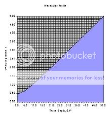
Waveguide profiles
Using an Excel worksheet, I've developed a routine to plot a profile. Variables include theta and "a", the waveguide throat. I had to go through some gyrations with page set-up, etc. to get it to scale. You should check this on your equipment. The depicted profile is for theta=45 and throat radius of 0.5"
I'll be glad to share this by e-mail.
Do I have my units right?
I'm trying to express R in terms of frequency and get hung up on units and math. Let's revisit post #5 from above and solve for the length of the device, R in meters for a specific frequency
Setting theta to 45 degrees, (sin (theta)*2) = 0.5
kR > 15.0 / (sin (theta)*2), so kR > 30
k = wave number, = w/c = (2 (pi) freq.)/ 345.6 m/s = frequency (0.018)
where w = angular frequency = 2 (pi) freq.
c = wave speed = 345.6 meter/sec
R > (30)/frequency(0.018) > frequency (0.54)
R > 1667 / frequency
If I have reduced this properly, R (1400 Hz) should be less than 1667/1400, or 1.19 meters.
My question for you, Dear reader, is whether I have reduced this properly. If so, we may proceed from there.
"The pic shows an oblate spheroid is mostly like a straight cone that goes to zero diameter at the back side"
After a ton of reading Earl's posts in the archives of diyspeakers.net and the High Efficiency Asylum, I see what's been confusing me about the shape.
Most of the waveguide is a cone. The OS only describes the transition section from the throat to the cone, which while small is crucial to minimizing the amount of HOM.
mgoedeke posted:
Aaahw...make me whine like a child...
Unfortunately that sheet is now gone
Aaahw...make me whine like a child...
mgoedeke said:@Ed: Excell is your friend. Just plot up the variables and you'll see fairly quickly where the apperture difraction limit comes in. I was just too lazy to solve it analytically so I drew up tables instead. Unfortunately that sheet is now gone.
Is anyone else building waveguides, or thinking about it?
Here's the spreadsheet that I use personally to build my waveguides.
An externally hosted image should be here but it was not working when we last tested it.
http://spicealley.net/~johnv/diyaudio/101506/oblate.zip
It's simple to use. Just plug in the coverage angle, the throat size, and the number of iterations. That's it!
Personally, I plot the segments using Visio or Xara, then print the segments. What I do with that is detailed earlier in this thread.
If you don't want to spend the time, I've included the printouts for a 66 degree by 99 degree waveguide. Basically print these segments up, cut out pieces of 1/4" foam or cardboard, and glue them together.
Here they are:
An externally hosted image should be here but it was not working when we last tested it.
http://spicealley.net/~johnv/diyaudio/101506/99x66 waveguide 1 of 4.pdf
An externally hosted image should be here but it was not working when we last tested it.
http://spicealley.net/~johnv/diyaudio/101506/99x66 waveguide 2 of 4.pdf
An externally hosted image should be here but it was not working when we last tested it.
http://spicealley.net/~johnv/diyaudio/101506/99x66 waveguide 3 of 4.pdf
An externally hosted image should be here but it was not working when we last tested it.
http://spicealley.net/~johnv/diyaudio/101506/99x66 waveguide 4 of 4.pdf
help! the attachment could notdownload
Have you get these attachement in your own computer?
I have found the link below which in turn contains links to each of the Geddes' papers referenced above.
Download
The 4 are grouped together near the bottom of the list.
Enjoy
Have you get these attachement in your own computer?
- Status
- This old topic is closed. If you want to reopen this topic, contact a moderator using the "Report Post" button.
- Home
- Loudspeakers
- Multi-Way
- Acoustic Waveguide