First of all thank-you to MJK for your wonderful mathcad models, and all the the contributors to TL threads. I'm going to build a test cabinet for the Peerless 850439 driver soon and wonder if anyone else is interested in using this driver in an MLTL. The goal is to surpass the performance of a 'textbook' bass reflex box. I've attached Martin's ML TQWT Design Worksheet with the published driver specifications and with my meanderings in case someone wants to look at the simulation results. I am very new to speaker design so if anyone is willing to suggest improvements I would gratefully welcome the advice. I will be getting the loudspeaker measured on a Clio or TEF system at work when it's assembled and can put up the results here if there's interest.
Attachments
You are using way to much stuffing to smooth out the ripple. If you need more than 0.3 lb/ft^3 to get the ripple below +-3dB, the design is flawed. However, you are on the right track. I think you are reaching a bit for a 5" driver, but not too much. Try L=40", eta=.23 and density=0.3. You can improve on this by using the "Ported" worksheet and moving the port up the pipe 4" or so. Position the port so as to minimize the peak in the port output at 600Hz. Then put some stuffing in the bottom of the pipe so as to round off the cut-off. Otherwise, the speaker will boom at cut-off.
Bob
Bob
Thanks Bob for your advice. I will tweak the ported worksheet for a while and post some simulation results in case anyone is following along.
I really want to get it right at the lower end of the range of human voice and can use a subwoofer to get the deeper bass. Some horn freaks have offered me a horn sub to put under the livingroom floor - I think I'll put it right under the sofa and not tell my wife.
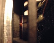
It's an interesting driver, on SL's list of good ones, with good power handling due to a fully ventilated engine-room, and it's small enough in diameter to behave itself at higher frequencies.
Just make sure to shop-vac the inside of any box you put one in because the voice coil is completely exposed. Here's a picture in case you're curious.
I really want to get it right at the lower end of the range of human voice and can use a subwoofer to get the deeper bass. Some horn freaks have offered me a horn sub to put under the livingroom floor - I think I'll put it right under the sofa and not tell my wife.
It's an interesting driver, on SL's list of good ones, with good power handling due to a fully ventilated engine-room, and it's small enough in diameter to behave itself at higher frequencies.
Just make sure to shop-vac the inside of any box you put one in because the voice coil is completely exposed. Here's a picture in case you're curious.
Attachments
>I really want to get it right at the lower end of the range of human voice and can use a subwoofer to get the deeper bass.
===
In this case you want to maximize acoustic gain down to ~65Hz, so considering its Xmax, a T/S max flat appears to be the Hot Ticket. FWIW, based on published specs, I get:
L = 26.625"
eta = 0.3707
So/Sl = 1.2889*Sd
rport = 1"
Lport = 3.75"
Stuffing to suit, with vent near/at the bottom, and a L-R 4th order active XO around 50Hz.
GM
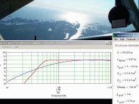
Thanks GM, I mjk'd the parameters that you suggested and with a bit of tweaking got results that look good in simulation. I will build this one soon and try it out. Out of curiosity, what would you suggest for 'fuller range' [no sub]? Would the design have to change much? Or is there not much to be gained? Here is a mjk simulation result, with beautiful Georgian Bay islands in the background.
Attachments
>Thanks GM, I mjk'd the parameters that you suggested and with a bit of tweaking got results that look good in simulation.
====
FWIW, I used the MLTQWT worksheet, so the sim accuracy decreases with increasing frequency since it assumes the vent is in the same location as the driver. Locate the vent at the same point as the driver in the ported worksheet, such as someone might do in a small design, and you'll see that it won't do many of the plots. Factor in we're not using measured specs and who knows what the response will be. Still, while mine was plenty good enough for the published specs, it never hurts to optimize it as best you can, just in case.")
====
>I will build this one soon and try it out. Out of curiosity, what would you suggest for 'fuller range' [no sub]? Would the design have to change much? Or is there not much to be gained?
====
Well, it would have to be a longer/larger cab with a longer vent and be either in a small room with lots of gain or at least stuck in the corners. Better to use two drivers in parallel and EQ them ~flat in-room.
Anyway, let us know how they turn out, and if you can, make some ~nearfield measurements to see how close the sim is.
====
>Here is a mjk simulation result, with beautiful Georgian Bay islands in the background.
====
So, are you a pilot/whatever, or just have a pretty background image?
GM
====
FWIW, I used the MLTQWT worksheet, so the sim accuracy decreases with increasing frequency since it assumes the vent is in the same location as the driver. Locate the vent at the same point as the driver in the ported worksheet, such as someone might do in a small design, and you'll see that it won't do many of the plots. Factor in we're not using measured specs and who knows what the response will be. Still, while mine was plenty good enough for the published specs, it never hurts to optimize it as best you can, just in case.
====
>I will build this one soon and try it out. Out of curiosity, what would you suggest for 'fuller range' [no sub]? Would the design have to change much? Or is there not much to be gained?
====
Well, it would have to be a longer/larger cab with a longer vent and be either in a small room with lots of gain or at least stuck in the corners. Better to use two drivers in parallel and EQ them ~flat in-room.
Anyway, let us know how they turn out, and if you can, make some ~nearfield measurements to see how close the sim is.
====
>Here is a mjk simulation result, with beautiful Georgian Bay islands in the background.
====
So, are you a pilot/whatever, or just have a pretty background image?
GM
Good point, I can [must] get the actual t-s params measured at work, and then redo the simulations. I will put some sine through the woofers for a few days first in case some break-in makes a difference.
I never could get rid of that low freq. shelf that appeared when the length of the TL was increased. Like Bob said it was reaching a bit too far. I am curious about how much different this design is expected to be, compared to the textbook bass-reflex golden ratio box, which winisd suggests to be 11.7 liters. BTW, I will be building that b-r box as well, for comparison to the MLTL, and will get them both measured nearfield on the CLIO at work. I too am curious to see how the measurements compare with the sims.
I'm not a pilot, but my aunt has an Archer II, coolest 55 year old I know, and she took my sister up to see her cottage from the air a few weekends ago. The photo made great wallpaper.
Thanks again.
>Good point, I can [must] get the actual t-s params measured at work, and then redo the simulations. I will put some sine through the woofers for a few days first in case some break-in makes a difference.
====
Then why on God's green earth are we wasting time using published specs?!
====
>I never could get rid of that low freq. shelf that appeared when the length of the TL was increased. Like Bob said it was reaching a bit too far.
====
Yep. Shelved responses are best suited for true sub woofers where Fb is <20Hz.
====
>I am curious about how much different this design is expected to be, compared to the textbook bass-reflex golden ratio box, which winisd suggests to be 11.7 liters.
====
I view the ML-TL alignments I normally do as optimized BRs for a given Vb, so Fb is a little lower, with a little more gain over a wider BW, and the vent(s) can be a bit smaller overall. The audible difference can be from very subtle to clearly superior depending on the driver's specs.
====
>BTW, I will be building that b-r box as well, for comparison to the MLTL, and will get them both measured nearfield on the CLIO at work. I too am curious to see how the measurements compare with the sims.
====
Looking forward to them.
====
>I'm not a pilot, but my aunt has an Archer II, coolest 55 year old I know, and she took my sister up to see her cottage from the air a few weekends ago. The photo made great wallpaper.
====
Indeed!
====
>Thanks again.
====
You're welcome!
GM
====
Then why on God's green earth are we wasting time using published specs?!
====
>I never could get rid of that low freq. shelf that appeared when the length of the TL was increased. Like Bob said it was reaching a bit too far.
====
Yep. Shelved responses are best suited for true sub woofers where Fb is <20Hz.
====
>I am curious about how much different this design is expected to be, compared to the textbook bass-reflex golden ratio box, which winisd suggests to be 11.7 liters.
====
I view the ML-TL alignments I normally do as optimized BRs for a given Vb, so Fb is a little lower, with a little more gain over a wider BW, and the vent(s) can be a bit smaller overall. The audible difference can be from very subtle to clearly superior depending on the driver's specs.
====
>BTW, I will be building that b-r box as well, for comparison to the MLTL, and will get them both measured nearfield on the CLIO at work. I too am curious to see how the measurements compare with the sims.
====
Looking forward to them.
====
>I'm not a pilot, but my aunt has an Archer II, coolest 55 year old I know, and she took my sister up to see her cottage from the air a few weekends ago. The photo made great wallpaper.
====
Indeed!
====
>Thanks again.
====
You're welcome!
GM
GM said: FWIW, I used the MLTQWT worksheet, so the sim accuracy decreases with increasing frequency since it assumes the vent is in the same location as the driver. Locate the vent at the same point as the driver in the ported worksheet, such as someone might do in a small design, and you'll see that it won't do many of the plots. Factor in we're not using measured specs and who knows what the response will be. Still, while mine was plenty good enough for the published specs, it never hurts to optimize it as best you can, just in case.
--------------
I don't think so. It is my understanding that the MLTQWT worksheet assumes the port to be at the closed end and sticking out of the pipe. In any case, using the "Ported" worksheet does make a major difference in the ripple by moving the port up ~10% of the pipe length. This usually allowed the stuffing density to be reduced to 0.1-0.2 lb/ft^3. I'm not convinced that I see the difference in measurements or hear the difference because of all of the other conamination in this frequency range, but I am now using properly placed round ports instead of rectangular ports at the bottom of the pipe. I'm be bringing a pair of these using FE167E's to Atlanta in October, so you can judge for yourself.
When actually designing a ported box, using the "Ported" worksheet to position the port has a major effect on suppressing the first 1/2 wave reflection. Again, I'm not sure you can hear the difference, but hey, why not do it right?
As far a MJK's worksheets blowing up, there are some singularities that will fail: Port length=0, eta=0, driver and port position the same. Just move the offending part by 0.01in and the worksheet will be happy.
Bob
Not wasted! I've learned much and will be within tweaking range when I get the driver parameters measured. It's tough doing this kind of learning after 10pm when the three 'angels' are finally asleep and my brain is like a pencil at the end of a long sentence, so I do appreciate both of your contributions here and in the many other threads.
Hi Bob
Which plot of "Ported" WS shows that peak?
TIA
JC
Bob Brines said:You can improve on this by using the "Ported" worksheet and moving the port up the pipe 4" or so. Position the port so as to minimize the peak in the port output at 600Hz.
Bob
Which plot of "Ported" WS shows that peak?
TIA
JC
Re: Port position
Hi.
Yes, I check this plot, but...
...density was 0.3 lbs. That explains.
I´m running simulations with Vifa PL-18. I´ll prepare zipped files and post here. Maybe you guys can check and correct me too.
Many thanks to all
JC
Hi.
teodorom said:Woofer and Terminus Far Field Sound Pressure Level Responses
Yes, I check this plot, but...
bzdang said:Set your stuffing density to zero while tweaking the port height.
...density was 0.3 lbs. That explains.
I´m running simulations with Vifa PL-18. I´ll prepare zipped files and post here. Maybe you guys can check and correct me too.
Many thanks to all
JC
>I don't think so. It is my understanding that the MLTQWT worksheet assumes the port to be at the closed end and sticking out of the pipe.
====
Yeah, I wasn't thinking clearly when I wrote that (unfortunately, an increasingly more common event), but I remember him saying the driver/vent sums at the driver location, so either way, accurary dwindles with increasing frequency as the vent terminus moves away from the driver regardless of which worksheet is used. Bottom line is I don't pay any attention to the plot above 600Hz. As always though, YMMV.
====
>In any case, using the "Ported" worksheet does make a major difference in the ripple by moving the port up ~10% of the pipe length. This usually allowed the stuffing density to be reduced to 0.1-0.2 lb/ft^3.
====
Yeah, when the driver is much closer to the top than I recommend, so we wind up with ~the same stuffing density though I normally put the vent near/at the bottom.
====
>I'm not convinced that I see the difference in measurements or hear the difference because of all of the other conamination in this frequency range, but I am now using properly placed round ports instead of rectangular ports at the bottom of the pipe.
====
Agreed, while his worksheets are more accurate than other programs in this area, they're still simple, and as we know, getting the damping right is essential to maximizing performance.
====
>I'm be bringing a pair of these using FE167E's to Atlanta in October, so you can judge for yourself.
====
I'm surprised! I figured the extra travelling distance would make it more trouble than it was worth, but glad you are, and looking forward to seeing you again! How's learning horn design coming along?
====
>When actually designing a ported box, using the "Ported" worksheet to position the port has a major effect on suppressing the first 1/2 wave reflection. Again, I'm not sure you can hear the difference, but hey, why not do it right?
====
Agree on the 'do it right' part, though I found that driver position is most important, then the vent location can be used primarily to adjust Fb damping. The trade-off being unable to get the driver at whatever height you want without usually making the pipe longer, with a cavity that needs filling. Fine by me though since cabs built with rigid materials need mass loading.
====
>As far a MJK's worksheets blowing up, there are some singularities that will fail: Port length=0, eta=0, driver and port position the same. Just move the offending part by 0.01in and the worksheet will be happy.
Bob
====
Yep.
====
>Not wasted! I've learned much and will be within tweaking range when I get the driver parameters measured. It's tough doing this kind of learning after 10pm when the three 'angels' are finally asleep and my brain is like a pencil at the end of a long sentence, so I do appreciate both of your contributions here and in the many other threads.
====
You're welcome! Understood, been there, done that, though only with two, but being one of each 'species' it oftened seemed like many more!
OK, then I'll rephrase it: you wasted my quality time WRT doing sims since if I want to update my driver data/sim base to possibly help others it will require more time on my part. You assume this effort negligible, and to a healthy person it is, but due to a variety of things every post I make is at best a very time consuming, uncomfortable event.
GM
====
Yeah, I wasn't thinking clearly when I wrote that (unfortunately, an increasingly more common event), but I remember him saying the driver/vent sums at the driver location, so either way, accurary dwindles with increasing frequency as the vent terminus moves away from the driver regardless of which worksheet is used. Bottom line is I don't pay any attention to the plot above 600Hz. As always though, YMMV.
====
>In any case, using the "Ported" worksheet does make a major difference in the ripple by moving the port up ~10% of the pipe length. This usually allowed the stuffing density to be reduced to 0.1-0.2 lb/ft^3.
====
Yeah, when the driver is much closer to the top than I recommend, so we wind up with ~the same stuffing density though I normally put the vent near/at the bottom.
====
>I'm not convinced that I see the difference in measurements or hear the difference because of all of the other conamination in this frequency range, but I am now using properly placed round ports instead of rectangular ports at the bottom of the pipe.
====
Agreed, while his worksheets are more accurate than other programs in this area, they're still simple, and as we know, getting the damping right is essential to maximizing performance.
====
>I'm be bringing a pair of these using FE167E's to Atlanta in October, so you can judge for yourself.
====
I'm surprised! I figured the extra travelling distance would make it more trouble than it was worth, but glad you are, and looking forward to seeing you again! How's learning horn design coming along?
====
>When actually designing a ported box, using the "Ported" worksheet to position the port has a major effect on suppressing the first 1/2 wave reflection. Again, I'm not sure you can hear the difference, but hey, why not do it right?
====
Agree on the 'do it right' part, though I found that driver position is most important, then the vent location can be used primarily to adjust Fb damping. The trade-off being unable to get the driver at whatever height you want without usually making the pipe longer, with a cavity that needs filling. Fine by me though since cabs built with rigid materials need mass loading.
====
>As far a MJK's worksheets blowing up, there are some singularities that will fail: Port length=0, eta=0, driver and port position the same. Just move the offending part by 0.01in and the worksheet will be happy.
Bob
====
Yep.
====
>Not wasted! I've learned much and will be within tweaking range when I get the driver parameters measured. It's tough doing this kind of learning after 10pm when the three 'angels' are finally asleep and my brain is like a pencil at the end of a long sentence, so I do appreciate both of your contributions here and in the many other threads.
====
You're welcome! Understood, been there, done that, though only with two, but being one of each 'species' it oftened seemed like many more!
OK, then I'll rephrase it: you wasted my quality time WRT doing sims since if I want to update my driver data/sim base to possibly help others it will require more time on my part. You assume this effort negligible, and to a healthy person it is, but due to a variety of things every post I make is at best a very time consuming, uncomfortable event.
GM
Ported box Vifa PL-18
OK this is my PL-18 sim in ported box WS
1. XO incorporates BSC, and is from Ken Perkins´ Nebula project
http://www.partsexpress.com/projectshowcase/nebula/nebula.html
2. PL-18 parameters are measured average of four
3. Port diam. radius is 1.32" obtained from Home depot PVC wire duct
Any correction and comments will be extremely appreciated
Thanks
JC
Re: Ported box Vifa PL-18
JC Fardo said:OK this is my PL-18 sim in ported box WS
Of coarse, the attached zip file
JC
Attachments
>Then why on God's green earth are we wasting time using published specs?!
>OK, then I'll rephrase it: you wasted my quality time WRT doing sims since if I want to update my driver data/sim base to possibly help others it will require more time on my part. You assume this effort negligible, and to a healthy person it is, but due to a variety of things every post I make is at best a very time consuming, uncomfortable event.
~~~~
Ouch, I'm feeling a bit scorched.
We're using published specs because that's what we have and that's what the first box is going to be built from [this weekend]. Measurements will have to wait until the bless'ed ones return from vacation next week. The measurements will be used to refine the next iteration. And I'm not sure how the actual t-s measurements of my drivers will be of use to anyone else, won't they have to measure their own, or settle for published specs?
I'm sorry that you experience discomfort from these activities, it's an unjust reward for a life of work and parenting. I don't assume that your effort is negligible, and I would gladly repay it with some cad modeling and rendering [my specialty] if that would be of assistance to you.
>Ouch, I'm feeling a bit scorched.
====
Yeah, well, I didn't have any luck with the more 'politically correct' way, which I've decided I've had enough of to last me till the end of this life anyway, so I may become 'persona non grata' pretty soon.
====
>We're using published specs because that's what we have and that's what the first box is going to be built from [this weekend]. Measurements will have to wait until the bless'ed ones return from vacation next week. The measurements will be used to refine the next iteration.
====
When I was teaching myself, experimentation was pretty much all that was available to a math challenged DIYer, and many of us did a small warehouse full of it, but to my way of thinking this is 'penny wise and pound foolish' reasoning in today's cheap hi -tech environment, or maybe a better phrase would be ' those who don't learn from history are doomed to repeat it'.
====
>And I'm not sure how the actual t-s measurements of my drivers will be of use to anyone else, won't they have to measure their own, or settle for published specs?
====
It depends. If they are 'close enough' to published specs then there's a good chance they have a decent QA program, but that's a huge assumption with some 'manufacturers'. Then there's the problem of them either not updating their website info in a timely fashion to reflect revisions done 'on the fly', or worse, never bothering to update them.
If the specs are way off, then while you can mod most any alignment to conform to the driver, it may compromise performance for the intended app so much it requires either a new cab, or worse, a different driver.
====
>I'm sorry that you experience discomfort from these activities, it's an unjust reward for a life of work and parenting.
====
Yeah, as some folks say, "life's a !@#$%, then you die". I prefer this one though, "growing old isn't for wimps!".
====
>I don't assume that your effort is negligible, and I would gladly repay it with some cad modeling and rendering [my specialty] if that would be of assistance to you.
====
Thanks for the offer, I may take you up on it some day! Anyway, glad you didn't take it too personally, it wasn't meant to be.
Please keep us updated on results, good/bad/indifferent of all the different alignments you try, and of course hopefully you'll share any measured specs.
GM
====
Yeah, well, I didn't have any luck with the more 'politically correct' way, which I've decided I've had enough of to last me till the end of this life anyway, so I may become 'persona non grata' pretty soon.
====
>We're using published specs because that's what we have and that's what the first box is going to be built from [this weekend]. Measurements will have to wait until the bless'ed ones return from vacation next week. The measurements will be used to refine the next iteration.
====
When I was teaching myself, experimentation was pretty much all that was available to a math challenged DIYer, and many of us did a small warehouse full of it, but to my way of thinking this is 'penny wise and pound foolish' reasoning in today's cheap hi -tech environment, or maybe a better phrase would be ' those who don't learn from history are doomed to repeat it'.
====
>And I'm not sure how the actual t-s measurements of my drivers will be of use to anyone else, won't they have to measure their own, or settle for published specs?
====
It depends. If they are 'close enough' to published specs then there's a good chance they have a decent QA program, but that's a huge assumption with some 'manufacturers'. Then there's the problem of them either not updating their website info in a timely fashion to reflect revisions done 'on the fly', or worse, never bothering to update them.
If the specs are way off, then while you can mod most any alignment to conform to the driver, it may compromise performance for the intended app so much it requires either a new cab, or worse, a different driver.
====
>I'm sorry that you experience discomfort from these activities, it's an unjust reward for a life of work and parenting.
====
Yeah, as some folks say, "life's a !@#$%, then you die". I prefer this one though, "growing old isn't for wimps!".
====
>I don't assume that your effort is negligible, and I would gladly repay it with some cad modeling and rendering [my specialty] if that would be of assistance to you.
====
Thanks for the offer, I may take you up on it some day! Anyway, glad you didn't take it too personally, it wasn't meant to be.
Please keep us updated on results, good/bad/indifferent of all the different alignments you try, and of course hopefully you'll share any measured specs.
GM
- Status
- This old topic is closed. If you want to reopen this topic, contact a moderator using the "Report Post" button.
- Home
- Loudspeakers
- Multi-Way
- PEERLESS 850439 in MLTL