Okay I got 4 (Four) x Fostex FE206E Drivers, and Two(2) Fountek JP2 Tweeters. Using all drivers ( two boxes obviously)) looking for suggestions. MLTL, DBR, FH what do you think?? Size suggestions, series or parallel.. All ideas welcomed. Got the drivers already.. Previously was thinking about a huge 180 litre DBR enclosure.. Now am not sure..
Please help.. Wanna use two fe206e's in one enclosure.. Heard lots of good stuff about JP2 also... SO looking forward to see if they play nice with each other.
Help!
Jeff
Please help.. Wanna use two fe206e's in one enclosure.. Heard lots of good stuff about JP2 also... SO looking forward to see if they play nice with each other.
Help!
Jeff
JeffG said:Okay I got 4 (Four) x Fostex FE206E Drivers, and Two(2) Fountek JP2 Tweeters. Using all drivers ( two boxes obviously)) looking for suggestions. MLTL, DBR, FH what do you think?? Size suggestions, series or parallel.. All ideas welcomed. Got the drivers already.. Previously was thinking about a huge 180 litre DBR enclosure.. Now am not sure..
Please help.. Wanna use two fe206e's in one enclosure.. Heard lots of good stuff about JP2 also... SO looking forward to see if they play nice with each other.
Help!
Jeff
fostex 206e is a full range driver (more or less), .. why would you want to use two of them in one box, .. me thinks you would have strange imaging effects (crude analogy, .. think of using 2 tweeters in one box)
if you were intending to use them as midranges and cross over to a tweeter, .. there are probably cheaper drivers for the purpose, ..plus you negate one of the biggest advantages of using single drivers ie. the lack of (or minimal) crossovers.
my suggestion: use each driver with / without the ribbon crossed high somewhere over 10K in a horn or box.
cheers
this may be what you want? D70
http://fullrangedriver.com/tiki-vie..._mode=commentDate_desc&topics_find=&forumId=1
http://fullrangedriver.com/tiki-vie..._mode=commentDate_desc&topics_find=&forumId=1
I like Navin's idea- any high frequency stuff from the rear driver won't make it around to the front to cause trouble! ")
From what I've heard through the grapevine though, the tweeter might be so good that it would be worth using a real crossover (low pass on the Fostex, high pass on the fountek) and cross over a bit lower than 8k.
From what I've heard through the grapevine though, the tweeter might be so good that it would be worth using a real crossover (low pass on the Fostex, high pass on the fountek) and cross over a bit lower than 8k.
navin said:one idea...
use the fostex in push push config and use the jp2 to fill in above 8-10k.
You beat me to it... push-push bipole... run the back ones all the way up, the 206s go up high enuff that you will want to roll them off no matter how high you bring in the ribbon... ideal would be a 3-amp setup, with a subrative XO on the front somewhere between 7->9k.
I've given consideration to similar systems a lot.
An externally hosted image should be here but it was not working when we last tested it.
more pics & explaination
dave
planet10 said:
You beat me to it... push-push bipole... run the back ones all the way up, the 206s go up high enuff that you will want to roll them off no matter how high you bring in the ribbon... ideal would be a 3-amp setup, with a subrative XO on the front somewhere between 7->9k.
I've given consideration to similar systems a lot.
An externally hosted image should be here but it was not working when we last tested it.
more pics & explaination
dave
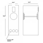
Thanks Dave. Looks like a very good idea. Couple of questions though.. Sorry.. Can I use a box like shown here. I dont know if I am up to the more complicated box designs. Also not sure what a subrative crossover. Also when "wired in phase" is this just parallel wiring? Do I really need three amps for this setup?? Sorry for all the questions.. Just dont know.. Thanks again?
Jeff
Attachments
No you don't need 3 amps -- that is just my way of making the XOver easy. A subtractive XO is an active XO, where (in this case) the low pass would be derived by subtracting the 2nd order high pass from the full-range signal -- it has the advantage of giving you one side rolling off faster than 1st order but still sums flat in both amplitude & phase. Probably the best paper on the technique is on the passlabs site.
If you dont want to go active, i'd be tempted to play with a 1st order series XO fairly high 9-10k but the ribbon might not be robust enuff.
With the active XO you can get 2nd order actively and then add another pole passively by putting a big cap a couple octaves below the actual XO point (and another if needed by decraeing the size of a coupling cap) to get an ultimate 3rd or 4th order filter on the tweeter. Those thin aluminum ribbons are really easy to turn into popped fuses
dave
JeffG said:How about the boix in the pic attached above? Will this work?
It should work (i didn't check the numbers)
dave
My suggestion is rather different..
2 box module similar to this:
http://www.stereotimes.com/speak050604.shtm
with the top module containing the ribbon and the bottom containing 2 206's
The bottom module will be a "back"-horn with a forward exit like the lamhorn but the exit "mouth" will extend all the way up to the top forward edge of the box (with no forward driver):
http://www.rlacoustique.com/lamhorn.htm
The 206's will be in two locations on the backhorn box. One will be upward firing, the other will be side firing adjacent to the upward firing driver. Both drivers will be located about midway in depth from the front of the baffle (or in this case the mouth exit of the horn) to the rear of the speaker.
The upward firing driver will be like this (in relation to the ribbon module):
http://www.boenicke-audio.ch/mediumNFeframe.html
The side firing driver will be adjacent to the upward firing driver like a zero box manger (except that the front baffle driver will not be on the front of the module, but instead on the top):
the black top module:
http://www.e-speakers.com/products/manger-loudspeakers.html
Additionally both 206's will utilize poly staws to direct the drivers rear radiation into the other drivers rear radiation. This means that the staws from the side firing driver move latterally and then bend up. The staws from the upward firing driver simply move downward (i.e. vertical with no bend). The exit point for the straws from both drivers will terminate with a half inch of space between them and acoustically "dump" into the compression chamber (that surrounds the staws and the drivers).
Both 206's will be run full range and the ribbon will utilize whatever type of network sums correctly acoustically with the two drivers.
Reasons for the design:
The ribbon module will allow better HRTF transfer because of its size and configuration (similar to a person's head). Additionally the ribbon module will give the point/line source benefits of specific localization. Conversly the upward driver will be omni-directional and will give the benefits of enhanced spatial perspective. The side firing driver will increase output.
The staw pipes containg the rear wave of the drivers do three things: 1. they effectivly eliminate high freq. reflections on the rear of the driver's cone, 2. they have a very low friction loss (acoustic resistance), 3. the way they are postiioned to each other reduces second order distrortion similar to the bi-polar approach seen by others.
The back-horn has several benifits. 1. It has the usual benefits of a horn - air impeadance matching and reduced excursion (which leads to lower distortion levels). 2. This horn relative to the drivers will have less acoustic time-delay because the exit is considerably forward of the drivers.
unfortuntly no..
imagine loading a speaker into a cylinder (pipe) - perhaps a pvc plumbing pipe that is 8 inches in diameter. Now fill that pipe with your average plastic straws and bunch them together to eliminate gaps so they will "stay-put". Essentially your creating a honey comb channel for the rear wave of the driver. For the top driver the length of the pipe should be fairly short (perhaps an inch past the driver's magnet) - for illustrative purposes lets say the pipe has a length of 6 inches. Additionally remember that I stated that this "pipe" will have NO bends (i.e. a straigt pipe with its exit downward.. vertical)
Graphically like this:
Top Driver
||
now imagine the cylinder of the side fireing driver. It is functionally the same except that it has a 90 deg. bend (often called an elbow bend for plumbers), where the pipe extends horizonatlly and the bend extends vertiacally.
Graphically like this:
Side Driver ==||
the upper portion of the "elbow" is the exit point for this pipe.
Now connect the two pipes acoustically (not physically) by leaving about a half inch of air space between them.
Graphically like this:
Top Driver
||
half inch air space between the two pipes
Side Driver ==||
....hope this comes out OK. It isn't.. no suprise. The forum is left justifying the "Top Driver" and its pipe "||".
no, not dense..
I looked back on it and realized that most of what I had written relied heavily on the pics in the links I provided - but obviously no link to the straw pipe.
by the way this is an EXCELLENT tech. (straw-pipe) to use on almost any design - even drivers exclusive to bass and with drivers that are rigid and dense (i.e. like accuton). You can eliminate the mechancial resistance that otherwise might plauge a design utilizing stuffing near the driver. This way you can have the decrease in impeadance near fs without the decrease in eff..
I think that both the beauhorn and the Reythem's (lowther designs) use this tech. in some fashion or another.
- Status
- This old topic is closed. If you want to reopen this topic, contact a moderator using the "Report Post" button.
- Home
- Loudspeakers
- Multi-Way
- ideas for fe206e and fountek JP2