Underhung with Faraday ring for low excursion
For low excursion drivers I believe an underhung motor with a thick Faraday ring to keep inductance both low and flat would be the lowest distortion design. A radial magnetic field is sometimes also used, including approximations like the Seas Hexdym(sp?)
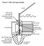
For high excursion drivers I believe the JBL Differential Drive motor which uses counter wound voice coils to nulify inductance would be the lowest distortion design. Anyone know when this motor patent expires?
For low excursion drivers I believe an underhung motor with a thick Faraday ring to keep inductance both low and flat would be the lowest distortion design. A radial magnetic field is sometimes also used, including approximations like the Seas Hexdym(sp?)
For high excursion drivers I believe the JBL Differential Drive motor which uses counter wound voice coils to nulify inductance would be the lowest distortion design. Anyone know when this motor patent expires?
Where would the Faraday ring be placed, and why would it lower inductance in that position?
What exactly is a "radial" magnetic field? Aren't all fields in the gap "radial" as in symmetrical when rotated around the pole piece axis?
Also, please check out the "Best Sounding Magnet" thread, below this one on the first page. I've some questions in the last page.
What exactly is a "radial" magnetic field? Aren't all fields in the gap "radial" as in symmetrical when rotated around the pole piece axis?
Also, please check out the "Best Sounding Magnet" thread, below this one on the first page. I've some questions in the last page.
Distortion :-
this statement can be said as correct that :
a power rating given to a driver , means that at all input levels of the driver rating within its specified limit , the driver :
1 ) should perform within the rating in long term use , robustness
2) should perform within very acceptable limits of distortion
3) and should show a certain limit of linearity in relation with the , actual accoustic power output increase to the input power supplied from the amps
without compression
the distortion is now adays mostly the deciding factor of the power rating including long term use
Here it needs to be devided in two sections
FIRST SECTION
in a broad context
distortion / you will find some speakers distorting _ much before the voice coil actually burns out
for eg - considering a driver in which this takes place :
a driver or if they are pro audio or drivers with simple pole vent cooling with the coils set in a tight magnetic gap - the coil can be on a paper former , oridinary wires used in the vc s
the vc s temperature will not rise easily normally 60 deg max , at this time it will distort
then this distortion is not from the vc temperature
(though in most books vc temp is one of the main source of distortion , why ? read on ....)
there are 3 basic types of non linearity in a transducer , these generate distortion , due to this distortion the voice coil heats up / at this moment no amount of cooling can help ,
the distortion effect from driver non linearities are such that it may lead to vc temp rise exponentially leading to vc burn out
the non linearities are
1. non linearity in the suspension mechanism
2. non linearity in the motor sturucture
3. non linearity caused when a coil moves in a permanent magnet motor structure (this is bound to happen even if the above 2 non linearities are addressed well )
to check for these non linearities while purchasing drivers
1. suspension non linearity
for the x - max of the driver you would like to purchase (or the one specified by the manufacturer) meaning you either know the x-max or have one in mind , then :
step a
push the driver cone downwards by that amount , it should go down linearly (the stiffness of the suspension increasing linearly) to the amount of the x-max
step b
pull the cone upwards towards you from beneath and it should come up to the specified x-max , again stiffness increasing linearly
if this does not take place the driver will distort -
unless the transducer manufacturer identifies specifically that such a non - linearity has been addressed , by making suitable compensations in the vc itself
2. motorstructure non linearity
fringe fields exists at the magnetic gap - the motor structure should be - sfg a symmetrical field geometry _ topology
therefore while purchasing a driver look if the motorstructure is - sfg or not
since expenses goes up in a sfg structure it will be specifically mentioned mentioned by the driver manufacturer , to inform customers
3. Non linearity caused when a coil moves in a permanent magnet motor structure
explaining this nature of non linearity is complex , anyone interested can see the sections on shorting rings in my thread
what is important
is that : -
has this been addressed by the transducer manufacturer
it is addressed by shorting rings placed in the motorstructure
since this too involves expence , and a considerable slow down in the manufacturing process this too will be specified by the driver manufacturer , to inform customers
-
the above are the main sources of distortion that determines the safe operating power of a driver , and are not the only sources of driver distortion (other sources of distortion are eddys , bottoming to name a few)
due to such complex stuff good driver manufacturers all over the world can be counted on finger tips
------------------------------------------------------------------------------------
SECOND SECTION
in good drivers context
good drivers are in which all the above criterias have been addressed
then the rise in vc temperature over long time use / the cooling efficiency comes in , and mostly all speaker failures of reputated manufacturers result from vc burn out (as mentioned by Navin)
mostly these limits are tested thoroughly and drivers tested to distruction and safe regions specified
i have found driver malfunction due to negligence of owners to go in for a service contract when pro audio drivers are used eg - movie halls , discs
in home audio , sources of reputated driver burn outs are :
a)
amp malfunction and dc component generation in the drive signal or signal clipping
speacially when high power speakers are used by under powered amps , many people do not even consider that a 35 w amp can damage a 100 w speaker system _ plain simple signal clipping can distroy well made drivers
if you have an under powered amp please ask a sound engineer to determine the clipping levels of your amp and restrict from running at clipping levels (in high end audio amps from manufacturers like Nad and onwards this is built in as standard , in the circuitry , therefore the prices)
b)
or the suspension parts have outlived _ may be the owner !
Suranjan Das Gupta
Transducer design engineer
hi
as for low excursions - an underhung will be the best - provided the 3 non - linearites i have mentioned above have been carefully addressed
for extreme excursions - XBL - 2 is very good / but it will lack the active correction - provided by the differential coil ,
Differential coil drive is very good too - as it activly corrects the voice coil position resulting it never to go into undesired over - excursion there-by reducing - distortion
Line source
seeing the way JBL is upgrading the Eons etc to DCD i really dont thinl the patent will be running out soon - Yamaha - car audio subs used a double mag DCD - I hope u have seen the info on it
suranjan das gupta
transducer design engineer
- Status
- This old topic is closed. If you want to reopen this topic, contact a moderator using the "Report Post" button.
- Home
- Loudspeakers
- Multi-Way
- Between the underhung and XBL^2 topology...