If it is true that there is a difference in SQ between series and parallel connections ( which perceived opinion seems to state ) and which would be my own opinion even if I personally cannot hear any difference; why are 16 Ohm drivers so hard to find?
I have built most of my systems WMTMW ( 3 way ) or WWMTMW ( 3.5 way ) and I have always thought that the amplifiers behave better ( cleaner : ie less distorion ) driving an 8 ohm load.
There may be another thing not so far mentioned , although this may be a glitch in Jeff Bagby's program, when modelling using JB's box program the final box volume is different when different wiring configurations are entered, using Jeffs program a parallel connection uses a much bigger box, almost 50% bigger than a series wiring.
Has any-one else come to this conclusion?
With identical drivers there is no change in Qes when
comparing series to parallel wiring.
The statement in the above JBL Brochure is wrong.
In the contrary the damping factor of a given amp
increases when load impedance is increased.
But with a usual solid state amp this is not an audible effect.
I often used series and series-parallel wiring. One thing i should
mention: Usually there are no identical drivers.
When comparing paralleled vs. series wired speakers which
differ in fs, the impedance curve of the series combination will
show the resonance peaks of every driver, the parallel wired
combination will look smother, because differing impedance
peaks between single drivers are balanced.
When using fullrange drivers in a line array like this
www.dipol-audio.de
parallel wiring is to be prefered in general.
Impedance peaks, even at frequencies higher than fs,
correlate with high voice coil velocity due to resonant conditions.
Parallel wiring will tend to balance voice coil velocity between
drivers, when resonance peaks are differing due to tolerances,
which is normally the case. The resonating driver simply gets
less current than its non resonating neighbour.
In the series circuit current through all drivers is the same,
and the resonating driver will see higher voltage at his clamps
than his non resonating neighbours, which tends to make things
worse, because power is always distributed to the driver which
behaves worst at a certain frequency ...
If series wiring cannot be avoided, it should be ensured, that the
units in series behave very similar or "equal" at best.
Have an emailed reply from Jeff Bagby; his answer is related to the parasitic circuit resistance ( I have measured this for the wiring in my sub box andwhile small 0.75 Ohms ) this small resistance must have some effect on Qes, if nothing else it reduces sound levels a smidgin.
Even big wire has some resistance, I ask again why more drivers are not made in 16R??
Even big wire has some resistance, I ask again why more drivers are not made in 16R??
LineArray said:....
In the series circuit current through all drivers is the same,
and the resonating driver will see higher voltage at his clamps
than his non resonating neighbours, which tends to make things
worse, because power is always distributed to the driver which
behaves worst at a certain frequency ...
So, how do you see this:
(It is just what I mentioned several posts back)
Can it at least do something good to the originally uneven voltage distribution?
how about this... To get down to the pure question of the topic...
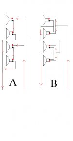
If you have a multiple of four drivers you can either configure series'd parallels, or parallel'd series.
to explain I have taken the time to draw a diagram in microsoft paint.
figure A is a configuration of parallel'd series.
figure B is a configuration of series'd parallel
Which do you think will sound 'better' and why?
personally I think B wins. The reason... inductance plays a major role in a driver's response, especially at high frequencies. With two drivers in series, the inductance doubles thereby causing higher frequencies to be attenuated more. By adding a second set of series drivers in parallel to the first(A) the overall inductance is the same as a single driver or, four drivers configured in pairs of two, paralleled, with the pairs connected in series.
the paralleled pairs connected in series would give half of the inductance per pair and add them back together with the series connection to equal the inductance of a single driver. In this case the inductance at any point does not go above the inductance of a single driver.
Maybe i'm just blowing smoke.
Attachments

Thanks!
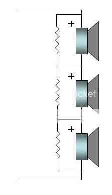
Well, but I got 3 drivers per side to deal with And I must wire them in series because I got no proper amp to handle low impedance
And this is for bass, so I don't worry much about the inductance.
http://www.diyaudio.com/forums/showthread.php?s=&threadid=117869
Well, but I got 3 drivers per side to deal with
And I must wire them in series because I got no proper amp to handle low impedance And this is for bass, so I don't worry much about the inductance.
http://www.diyaudio.com/forums/showthread.php?s=&threadid=117869
The difference batween A and B is that A lacks an extra wire between the mid connection points of its two driver chains which in B first ties two in parallel.
This extra wire averages two drivers before any are driven in series.
When driven in plain series, as in A, each driver difference can modify its own partner to a greater extent.
The resistors in CLS's drawing are going to help damp any audible impedance change interactions due to individual driver reactances. The bass notes cannot sound the same as when drivers are connected in parallel, though if 'needs must', then resistors across each helps to minimise series induced transduction losses.
Cheers ....... Graham.
Simple answer
If room and other factors is not taken into consideration
You are doubling the voice coil inductance and DCR of driver.
If we calculate things
Sound difference is more linear high rising impedance but then more peaky resonant impedance.
Means, if you use woofer, it will make bass more bassy and treble roll off.
Qts, Qms and other thiele paramentes also changes.
But the thing is, you can do it, but then design a series notch filter with specific resistance to get the driver peak to old value ratio.
Then woofer will act like more woofer.
But I will do that in isobaric chamber with very specific circuit to sound good.
It underdamps LF and slightly damps the HF.
Its a good concept in IEMs but doing it on full size speaker is not recommended until or unless you can stimulate the driver characteristics. Plus amplifier will have harder time putting juice into the speaker and due to that peak, it can also oscillate.
This is my experience, other may vary.
Tweeter becomes smooth though
A long time ago, Elliot Sound Production did a series vs parallel article.
Series vs. Parallel Crossover Networks
Great article. Long. A must read. I hope the link works.
Esp input a square wave into each crossover. They plotted the output.
The series crossover output the exact same square wave. If we draw an analogy to music; female voice in, same female voice out.
The parallel crossover output has little bumps. Female voice in, slightly altered female voice out. For some of us, we can hear this little variation. For others, no difference.
Salk Sound builds series crossover speakers. Do a search on what their owners say.
Attachments
Let's look at your choice of amplifiers.
The first breakdown is obvious. Tube vs Solid State.
Tube amplifiers are current sources.
Solid State amplifiers are mostly voltage sources.
However, there are a few Solid State amps that use current source output chips. This number is low, so we'll assume you don't have one. For those that do, SS current source behave more so like tube amps.
My amplifiers are the Atma-Sphere MA-1 tube amps. 140 watts into 8 ohms;
8 ohms 140w
4 ohms 120w
2 ohms no rating. You must use an Auto-former. This will increase the impedance seen by the amps. With a Tube amp, parallel wiring presents a lower impedance. Not a good idea.
Let's go in the other direction:
8 ohms 140w
16 ohms 160w
32 ohms 160w
64 ohms 160w
128 ohms 160w My woofer choice, the Acoustic Elegance TD15H+ are ~ 120 ohms at fs of 20Hz. In box fs is closer to 35Hz. My next speaker will use dual TD15H+'s, and series wiring will be my likely choice. However, test listen, test listen, etc. Never make an assumption.
Let's look at Solid State, 140 watts at 8 ohms:
8 ohms 140w
4 ohms 280w
2 ohms 560w
1 ohm 1120w ? This is simply an example. There are few amplifiers like this.
Let's go in the other direction:
8 ohms 140w
16 ohms 70w
32 ohms 35w
64 ohms 17.5w
128 ohms 8.25w If you use a solid state amp, you would never double this impedance by wiring is series. There would be less output.
Conclusion;
If you have a Solid State amp, you will get more power (volume) with a parallel wiring scheme.
If you have a Tube amp, you will get more power (volume) with a series wiring scheme.
Let's look at your choice of amplifiers.
Let's not forget speaker efficiency. Each time you double the driver count, you should get a 'free' 3dB SPL boost on top of the 3dB one might expect based on a doubling of power. At least in the bass where the phases are all nicely aligned.
35W = 4 x 8.75Let's go in the other direction:
8 ohms 140w
16 ohms 70w
32 ohms 35w
64 ohms 17.5w
128 ohms 8.25w If you use a solid state amp, you would never double this impedance by wiring is series. There would be less output.
Let's say we've got 4 amplifiers delivering 8.75W each to a different 8 ohm speaker.
Amplitude a = 0dB
a × 2^2 => + 12dB
But to get +12db for a single speaker:
Power p = 8.75W
p × 2^4 = 140W
So it's about the same power wise. But performance?
My intuition says, firstly, a modest 9W each into 4 array elements would blow the 140W solo speaker out of the water in terms of distortion.
Wiring them in series would risk voltage hogging. Bad for V amplifiers.
Wiring them in parallel would risk current hogging. Bad for I amplifiers.
Thinking out loud here...
In parallel: any anomalous back-emf (current attempting to induce a voltage) would tend to get shorted out by the amplifier, preventing crosstalk. It works if the voltage is tightly regulated. A current amp might behave strangely and reflect current through the other speakers (tapping 1 speaker would cause the others to move). I would imagine some weird feedback and maybe some oscillation.
In series: anomalous back-emf such as tapping fingers on the cone, would alter voltages locally. A voltage amp would reflect that signal onto the other drivers, similar to above. Conversely, a current amplifier would regulate the current, keeping it at zero (or whatever the audio signal happens to be) for the whole array. Finger tapping would not propagate.
I guess either option should be about the same, but I'm leaning towards a current amplifier running the array in series.
2) convenience. Slim wiring.
1) competing speaker design dogmas. Low output impedance for reflecting box reflections, which has the side effect of making them more and more resonant as the driver's Qts gets closer to zero. High output impedance for doing nothing about box colourations, except mechanically with wool or just not having a box.
Thank you abstract. Great response.
Taking it sideways. How many times have we read; such and such a speaker was voiced with such and such an amp.
As do-it-yourself'ers, we need to first figure out what floats our boat. Are we solid state fans, are we tube fans? Everyone is different, and no one design is perfect.
Taking it sideways. How many times have we read; such and such a speaker was voiced with such and such an amp.
As do-it-yourself'ers, we need to first figure out what floats our boat. Are we solid state fans, are we tube fans? Everyone is different, and no one design is perfect.
- Status
- This old topic is closed. If you want to reopen this topic, contact a moderator using the "Report Post" button.
- Home
- Loudspeakers
- Multi-Way
- Series vs. parallel sound quality