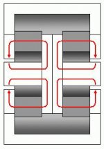
Get a a pair of identical drivers and make sure the rear polepieces are nice and smooth so they make good contact. Then you have to put a steel (ideally tubular) polepiece from the periphery of the one front polepiece all the way to the other.
The idea is that both the magnet systems are in parallel but the voice coils are driven opposite phase so while one magnet is having it's field pushed one way the other magnet is getting the opposite treatment. The external polepiece transfers this rude behaviour across from one side to the other and hopefully the nett effect is zero.
(See my addition to your drawing)
Interesting idea, but I'm not so sure it will work as you hope. Though the drivers are back-to-back and their top plates are bridged with a magnetic pathway, still there is only a little magnetic coupling between the two circuits--they'll operate largely independently. Perhaps there would be some benefit, but even though the two motors could share some flux, each energized VC will still be trying to reverse its local B field.
OTOH, maybe it would work better than I'm imagining....
Attachments
Not sure if we are talking about the same thing because I don't really know what a B field is.Bill F. said:Perhaps there would be some benefit, but even though the two motors could share some flux, each energized VC will still be trying to reverse its local B field.
 If both the voice coils are moving outward or inward at the same time then I imagine what you say would be so, but if they are both moving to the left or both moving to the right as in an isobaric setup then I still get this warm cozy feeling about the whole thing.
 Sorry for the jargon... The B field is the flux across the gap, the B component in the force equation F=BLi.
I think I see what you're shooting for here, but I fear that no matter how the VCs are energized, the two magnetic circuits will still tend to operate independently without much mutual benefit.
As I perceive it, the bridge between the two circuits is a largely unused magnetic pathway. Only weak leakage flux typically projects from the outer perimeter of the top plate, and linking two top plates of like polarity will result in no real flux flow, even when considering the coil fields. The coil fields will still try to reverse flux through their local magnets.
I think it's the use of two local circuits that's the weakness. The cornerstone of the Differential Drive and Flux Fulcrum concepts is to pit two coils against each other in a single magnetic pathway, so the net effect on the magnet's flux contribution is zero.
However, I do think your design is clever thinking, and I allow that I may not be giving it proper consideration...
Re: NdFeB or Field Coil
Also, how exactly do Faraday rings stabilize the flux, and is that the same thing as reducing flux modulation? Furthermore, how does ATC's SLMM compare to copper plating (a la Seas' Excel line) and Faraday rings with respect to efficacy?
Another thing... are field coils affected by flux modulation at all?
Wait, still another question - in ATC's paper about their SLMM material, they state:
"When eddy currents are allowed to circulate in the system, they oppose the magnetic field producing them (i.e. that from the coil) and ‘cancel out’ much of the self-inductance. With the S.L.M.M. in place, eddy currents are suppressed and the self-inductance (i.e. the impedance) goes up."
Do eddy currents affect the inductance (i.e. the T-S parameter)? If so, wouldn't using SLMM be a compromise?
Last thing - other than using JBL's DD topology, how can one decrease the inductance of a driver? Would plating the gap face with copper or silver work, and if so, how much would the flux density (i.e. x Tesla) suffer?
Thanks for your time, :beer;
Sorry to revive this post from the abyss, but could you explain in more detail how flux modulation occurs, and why exactly ferrite magnets are more susceptible?LineSource said:The current in the voice coil generates a magnetic field that can "appear" to reduce the pole piece magnetic field and create distortion. Ceramic magnets are more susceptible to this reverse field modulation than NdFeB or Alnico. And this BL modulation distortion is much greater in high power woofers than low wattage tweeters/mids.
Also, how exactly do Faraday rings stabilize the flux, and is that the same thing as reducing flux modulation? Furthermore, how does ATC's SLMM compare to copper plating (a la Seas' Excel line) and Faraday rings with respect to efficacy?
Another thing... are field coils affected by flux modulation at all?
Wait, still another question - in ATC's paper about their SLMM material, they state:
"When eddy currents are allowed to circulate in the system, they oppose the magnetic field producing them (i.e. that from the coil) and ‘cancel out’ much of the self-inductance. With the S.L.M.M. in place, eddy currents are suppressed and the self-inductance (i.e. the impedance) goes up."
Do eddy currents affect the inductance (i.e. the T-S parameter)? If so, wouldn't using SLMM be a compromise?
Last thing - other than using JBL's DD topology, how can one decrease the inductance of a driver? Would plating the gap face with copper or silver work, and if so, how much would the flux density (i.e. x Tesla) suffer?
Thanks for your time, :beer;
Buncha great questions that deserve thorough answers! I'll take a minute to have a crack at your main one...
Lenz's law, named after the nineteenth century Russian scientist Heinrich Lenz: The emf induced in an electric circuit always acts in such a direction that the current it drives around the circuit opposes the change in magnetic flux which produces the emf.
IOW, when it comes to magnetic fields, conductive materials hate change.
So, let's take the example of a loudspeaker motor. Ideally, the modulated field created by your voice coil would interact only with the B field in the gap. Trouble is, a respectible gap field usually requires ferromagnetic materials to be nearby, within easy reach of the coil field. When those materials are electrically conductive, they conduct eddy currents when their flux flow is modulated (ala Lenz), and hysteretic behavior spoils the party. (Note: eddy currents are not necesarily the enemy, hysteresis is.)
So the savy loudspeaker designer must find a way to protect the electically conductive ferromagnet parts of the motor from flux modulation by the coil field.
The Faraday (shorting) ring method:
In its simplest, most comprehensive application, sheath the pole piece in copper. Copper is very conductive of eddy currents, but it is not ferromagnetic, so its eddy currents will not create hysteretic behavior. Instead, the eddy currents are beneficial in that they flow in such a direction that they create a reciprocal field that cancels the modulation of the coil field, effectively shielding all material behind it from the modulating field.
Potential drawbacks include increased motor damping (reduced Qes) and increased gap spacing to allow for the thickness of the faraday ring.
The ATC/SLMM method:
Put some distance between the coil field and the conductive ferromagnetic materials by lining the magnetic gap with what they call SLMM (which I don't know exactly what is, though I'd really like to ) The upshot, as I understand it, is that SLMM conducts magnetic flux reasonably well, but it is very resistant to the flow of electricity. So while the coil field can modulate it and even flip a few of its domains, those domain flips don't create hysteretic currents. And you don't get reduced damping in the bargain, so it's great for bass. Brilliant, really.
Potential drawbacks include the limited permeability of SLMM and quicker inductance rolloff with rising frequency
Went really long here already and I gotta run.
Also, how exactly do Faraday rings stabilize the flux, and is that the same thing as reducing flux modulation?
Lenz's law, named after the nineteenth century Russian scientist Heinrich Lenz: The emf induced in an electric circuit always acts in such a direction that the current it drives around the circuit opposes the change in magnetic flux which produces the emf.
IOW, when it comes to magnetic fields, conductive materials hate change.
So, let's take the example of a loudspeaker motor. Ideally, the modulated field created by your voice coil would interact only with the B field in the gap. Trouble is, a respectible gap field usually requires ferromagnetic materials to be nearby, within easy reach of the coil field. When those materials are electrically conductive, they conduct eddy currents when their flux flow is modulated (ala Lenz), and hysteretic behavior spoils the party. (Note: eddy currents are not necesarily the enemy, hysteresis is.)
So the savy loudspeaker designer must find a way to protect the electically conductive ferromagnet parts of the motor from flux modulation by the coil field.
The Faraday (shorting) ring method:
In its simplest, most comprehensive application, sheath the pole piece in copper. Copper is very conductive of eddy currents, but it is not ferromagnetic, so its eddy currents will not create hysteretic behavior. Instead, the eddy currents are beneficial in that they flow in such a direction that they create a reciprocal field that cancels the modulation of the coil field, effectively shielding all material behind it from the modulating field.
Potential drawbacks include increased motor damping (reduced Qes) and increased gap spacing to allow for the thickness of the faraday ring.
The ATC/SLMM method:
Put some distance between the coil field and the conductive ferromagnetic materials by lining the magnetic gap with what they call SLMM (which I don't know exactly what is, though I'd really like to
) The upshot, as I understand it, is that SLMM conducts magnetic flux reasonably well, but it is very resistant to the flow of electricity. So while the coil field can modulate it and even flip a few of its domains, those domain flips don't create hysteretic currents. And you don't get reduced damping in the bargain, so it's great for bass. Brilliant, really. Potential drawbacks include the limited permeability of SLMM and quicker inductance rolloff with rising frequency
Went really long here already and I gotta run.
To answer one of YOUR questions, I belive SLMM is actually a type of permalloy with a medium-to-high concentration of nickel (anywhere from 50-80%).
Take a look at this: http://www.thyssenkruppvdm.com/_pdf/Magnifer8105_e.pdf
Pretty low saturation density, though: 0.7T, if that's what saturation induction means.
I see how a dia/paramagnetic electrically-conductive metal coating on the gap faces might work, like in this diagram: http://ldsg.snippets.org/graphics/lambdamotor.jpg
... but how does the ring work in this diagram? http://www.audioheritage.org/images/projectmay/technology/sfg.jpg
Fantastic thread and posts everyone! Thank you so very much.
P.S.:
P.S.:
"Lenz's law, named after the nineteenth century Russian scientist Heinrich Lenz"
Hmm, with that characteristical Russian first name "Heinrich" and last name "Lenz" !
Hmm, with that characteristical Russian first name "Heinrich" and last name "Lenz" !
Maybe his was one of the thousands of German families Catherine the Great brought to Russia with promises of land?
To answer one of YOUR questions...
Thanks for that info. Are you pretty sure that IS the stuff? The resistivity is lower than I thought it would be...
... but how does the ring work in this diagram?
The same way as the full-length faraday ring, I believe. It resists deformation of the B field by conducting eddy currents. It's just acting at a different point in the circuit to avoid increasing gap spacing. You'd have to do some dynamic FEA sims to see exactly how it works, but I suspect it represents a tradeoff and doesn't work quite as efficiently or over the same bandwidth as the full-lengh faraday ring.
There are a couple of older threads on the same topic. I think Barkhausen noise is not a major issue. Enemies are:
1. Field modulation in the iron system, causing nonlinearity due to hysteresis and maybe also Barkhausen noise (steel is not exactly a good electrical conductor!).
Countered by shielding the iron from the VC's field (copper capsule) or by driving the iron well into saturation. The latter requires an AlNiCo or Nd magnet and a design that does not strive for efficient use of the magnet but has the aim to saturate the iron near the gap while keeping a reasonably symmetric field. The field still penetrates the iron, but it cannot change its magnetization if the modulation is smaller than the excess (beyond saturation) permanent field.
2. Inductance: the pole piece acts as an iron core to the VC, increasing its inductance and hence inhibiting current flow. The VC current will modulate the magnetization of the pole piece nonlinearly (because it is near saturation), giving rise to IMD. Also, unless the pole piece is very long, the inductance will depend on the displacement of the VC.
Countermeasures: same as 1, either screen the pole piece or saturate it so it cannot react to an external field (giving it an effective permeability of 1 for small external fields).
3. Modulation of the field inside the permanent magnet: this becomes only relevant if the iron system can pass on the modulation. A copper shielding will surpress this, and even without shielding the iron hysteresis and Barkhausen noise is probably a bigger issue than the same effects in the ceramic magnet.
=> The Watkinson statement is only partly true. The main problem is not Barkhausen noise in the magnet. On the other hand, a Nd magnet is one way to surpress these problems in the iron system. Unfortuntately, most commercial designs with Nd magnets do not saturate the iron, i.e. they are designed for maximum efficiency at minimum cost, not low distortion.
The copper ring, by the way, is used a lot in Peerless drivers. It lets the pole piece be modulated, but keeps the modulation from spreading into the rest of the iron system and the ceramic magnet. You will find that these drivers exhibit an inductance that is not much lower than in similar drivers without any screening. Still, their distortion performance is almost as good as in fully screened systems.
Bill F. said:I also have another design that incorporates coil inductance cancellation, if you can picture that.
It would be interesting to compare this with a standard topology driver in terms of Barkhausen phenomena.
Is this what is used in the Manger (www.manger-msw.com)? If you go to the English version an then to the "research" menu, there is a talk Daniela Manger has given to the ASA. From this is this excerpt:
"The presented bending wave transducer, which is protected as Manger Sound Transducer,
has an electrodynamic motor working with two voice coils on one layer. Mechanical in serial
operation and electrical in parallel it is possible compensating for emf which is generated by
the voice coil movement. The inductivity of the voice coil is 18µH, about 1000 times smaller
than a conventional voice coil inductivity. The total weight of the voice coil is only 0.4 g. By
this specifications the influence of the motor is only resistive in the interesting frequency
range."
It looks a lot like the Adire XLB^2 motor, with to voice coils situated at the top and bottom edges of the gap. However, the ridges that concentrate the field to the top and bottom in the Adire concept are missing. Also, the winding sense and wiring may be diffent in the Manger. I have yet to find the time to understand how it cancels the VC inductance. I have downloaded the German patent applications from the early 70s, but have not had time for a careful reading yet.
Also, the winding sense and wiring may be diffent in the Manger. I have yet to find the time to understand how it cancels the VC inductance.
I don't think that it actually cancels anything. But the following physical/mathematical properties of coils may be in use:
If you parallel two coils of same Inductance you end up with half the inductance.
If you half the amount of windings you end up with a quarter of the original inductance.
If you do both at once (which I assume Manger is doing) you will end up with 1/8 of the original inductance.
Regards
Charles
Good points, Capslock.
Another point that should not be overlooked for its obviousness is the advantage of high efficiency. At a given SPL/freq., a high-efficiency driver will generally have a greater B to Li ratio, so the coil field is smaller than that of a less efficient driver at the same SPL/freq., and therefore is flipping fewer domains in the return circuit.
Another point that should not be overlooked for its obviousness is the advantage of high efficiency. At a given SPL/freq., a high-efficiency driver will generally have a greater B to Li ratio, so the coil field is smaller than that of a less efficient driver at the same SPL/freq., and therefore is flipping fewer domains in the return circuit.
phase_accurate said:
I don't think that it actually cancels anything. But the following physical/mathematical properties of coils may be in use:
If you parallel two coils of same Inductance you end up with half the inductance.
If you half the amount of windings you end up with a quarter of the original inductance.
If you do both at once (which I assume Manger is doing) you will end up with 1/8 of the original inductance.
Regards
Charles
Looking at the physical size of the pole piece, and even considering the short winding height, it seems like a 2-3 orders of magnitude reduction was achieved, so there must be something else.
I have the PDF's of the old Manger applications. If you want, I can e-mail them to you (but they are pretty big).
Does anybody have a drawing of the JBL differential drive magnet structure? I have googled and only found an article devoid of figures. Apparently, the use two gaps of opposing flux, which would seem to make for a very interesting return system design.
Referring to the discussion earlier in this thread, why would copper sleeving lower Q_t? Unlike an Al-VC former moving in the field of the gap, the sleeving is not moving, and it only mirrors the currents in the VC instantaneouly. This would do nothing but inhibit currents in the VC, i.e. increase its inductance, except that you would have the very same eddy currents in the pole piece even without the sleeving. Coppers resistance being 14x lower than typical steel, the copper does nothing but to concentrate the currents to the surface of the pole piece.
Besides, as was noted correctly, it increases the effective gap width, increasing Q_e.
http://www.diyaudio.com/forums/attachment.php?s=&postid=305093
Though the coils act in unison, otherwise the forces would cancel each other out.
Though the coils act in unison, otherwise the forces would cancel each other out.
hi
Capslock
The Manger design is essentially - reverse of XBL - 2 and a far easier approach
as machining the ridges in the xbl - 2 motor structure with 1008 soft steel - involves cnc lathe machining
(though possible as oem any extreme design here in India even in small numbers anyone interested contact me ! includes hydrogen annealing )
it is the same principle of either a +ve or a -ve excursion from rest position will result the coil entering the same magnet field area - keeping the ratio of BL at rest position to the limit of x- max same / therefore the astounding graphs of BL linearity - in the klippel tests of these drivers !
suranjan das gupta
transducer design engineer
Capslock
It looks a lot like the Adire XLB^2 motor, with to voice coils situated at the top and bottom edges of the gap. However, the ridges that concentrate the field to the top and bottom in the Adire concept are missing. Also, the winding sense and wiring may be diffent in the Manger. I have yet to find the time to understand how it cancels the VC inductance. I have downloaded the German patent applications from the early 70s, but have not had time for a careful reading yet.
The Manger design is essentially - reverse of XBL - 2 and a far easier approach
as machining the ridges in the xbl - 2 motor structure with 1008 soft steel - involves cnc lathe machining
(though possible as oem any extreme design here in India even in small numbers anyone interested contact me ! includes hydrogen annealing )
it is the same principle of either a +ve or a -ve excursion from rest position will result the coil entering the same magnet field area - keeping the ratio of BL at rest position to the limit of x- max same / therefore the astounding graphs of BL linearity - in the klippel tests of these drivers !
suranjan das gupta
transducer design engineer
capslock,
check out the attachments in this thread:
http://diyaudio.com/forums/showthread.php?s=&threadid=38047
Cheers,
BK.
PS: darn, these anglos have been faster encore. Je me souviens.
check out the attachments in this thread:
http://diyaudio.com/forums/showthread.php?s=&threadid=38047
Cheers,
BK.
PS: darn, these anglos have been faster encore. Je me souviens.
Hi
Ciclotron -
nice idea - another approach to an active / semi active - inductance linearity set up is
the Alumunim shorting ring - embedded in the motor structure is shorted by a wire (soldered to it - taken out of the back plate of the motor stucture) - and grounded to the - ve terminal of the driver
Suranjan Das Gupta
Transducer Design Engineer
Ciclotron -
If I was any good at dismantling and re-assembling a loudspeaker, an experiment I would love to try is - count the number of turns of wire on the voice coil and then wind this same amount of turns in antiphase on the centre polepiece right down away from the voice coil. Then put this winding in *series*with the voice coil.
nice idea - another approach to an active / semi active - inductance linearity set up is
the Alumunim shorting ring - embedded in the motor structure is shorted by a wire (soldered to it - taken out of the back plate of the motor stucture) - and grounded to the - ve terminal of the driver
Suranjan Das Gupta
Transducer Design Engineer
- Status
- This old topic is closed. If you want to reopen this topic, contact a moderator using the "Report Post" button.
- Home
- Loudspeakers
- Multi-Way
- Best Sounding Magnet!