The nifty webpage www.diysubwoofers.org has the formulas for calculating frequency response curves for sealed and ported systems. Cool. After about four minutes playing with Python I was making lovely FR plots.
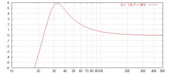
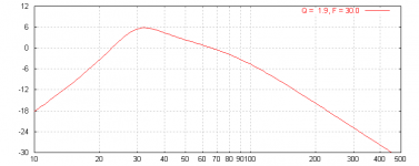
Now then, I want to add in the effect of bass boost. Say for example I have a plate amp that has a 6 dB boost at 30 Hz with a Q of 1.7. What now? How do I adjust the FR curve? Anyone know the formula? Or know where I can find it?
Now then, I want to add in the effect of bass boost. Say for example I have a plate amp that has a 6 dB boost at 30 Hz with a Q of 1.7. What now? How do I adjust the FR curve? Anyone know the formula? Or know where I can find it?
So you have something like:
Vb = net box volume (litres)
Fs = driver resonance frequency (Hz)
Qts = driver Q at system resonance
Fb = box tuning frequency (Hz)
Ql = box losses (Ql=7 can be assumed for most cases)
then,
Fn2 = (F/Fs)^2
Fn4 = Fn2^2
A = (Fb/Fs)^2
B = A/Qts+Fb/(Fs*Ql)
C = 1+A+(Vas/Vb)+Fb/(Fs*Qts*Ql)
D = 1/Qts+Fb/(Fs*Ql)
dBmag = 10*LOG(Fn4^2/((Fn4-C*Fn2+A)^2+Fn2*(D*Fn2-B)^2))
Multiply the result inside the log expression by:
ff2/sqrt((1-ff2)^2+(ff2/Q^2)) then take the log........
where ff = F/Filter freq
ff2 = ff^2
Q is self explanatory
BTW, a sealed box can be modeled with the above equations by setting Fb=0.
Have a great day.....
Beauty! I think I've got it, and the first test graphs look reasonable. Let me just re-phrase what you said to be sure I've got it.
First express the unequalized response curve in the form,
dbMag(f) = 10*log10(P(f))
where the form of the function P depends on the alignment type (sealed box, or whatever).
Let
Q = filter_Q
ff(f) = f/Filter_freq
ff2(f) = ff(f)^2
M(f) = ff2(f)/sqrt((1-ff2(f))^2+(ff2(f)/Q^2))
Then the equalized curve is defined by
eqdbMag(f) = 10*log10(M(f)*P(f))
Do I got it?
Ron E said:Yup.
Post a screenshot of your results, and the parameters you entered, I should be able to model it and compare.
Will do.
BTW, You can model a 2nd order lowpass with:
1/sqrt((1-ff2)^2+(ff2/Q^2))
Eh? I don't know what that means.
Ron E said:boost = 20 * log(Q) ;-)
Lowpass filters cut the highs, like the crossover built into most plate amps....
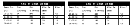
I think I get it. I think you are saying that the info in the charts below is redundant. The so-called "boost" is actually a low-pass shelf filter. If there were sufficient decimal places in the charts, I could calculate Q from boost or vice versa. Example: A "boost" of exactly 5 dB will actually (and inevitably) have a Q of 1.7782794100389228. Right?
Attachments
Clarifying:
The boost is a 2nd order highpass filter with the equation:
A(f) = ff2/sqrt((1-ff2)^2+(ff2/Q^2))
...and yes, the Q determines the dB of peaking.
20*log10(1.778)=5dB
The shape of the curve is defined by your box design, the peaking filter and the crossover frequency. There are a lot of independent variables now, so the system can get complicated pretty fast. When applying a boost circuit, it is best to apply boost at the Fb of the vented system.
Remember, a lowpass passes the lows and cuts the highs, and a highpass passes the highs and cuts the lows. The peaking lowpass filter here cuts the lows below trhe tuning frequency and protects the vented driver below resonance. This is better known as a 6th order alignment.
The crossover is a lowpass filter - and a 2nd order lowpass has the equation:
B(f) = 1/sqrt((1-fc2)^2+(fc2/Q^2)), where :
fc2 = (F/F_crossover)^2
The response of the woofer + HP filter + LP crossover is then
20*log10(A(f)*B(f)*P(f))
Ron E said:Clarifying:
The boost is a 2nd order highpass filter with the equation:
A(f) = ff2/sqrt((1-ff2)^2+(ff2/Q^2))
...and yes, the Q determines the dB of peaking.
20*log10(1.778)=5dB
The shape of the curve is defined by your box design, the peaking filter and the crossover frequency. There are a lot of independent variables now, so the system can get complicated pretty fast. When applying a boost circuit, it is best to apply boost at the Fb of the vented system.
Remember, a lowpass passes the lows and cuts the highs, and a highpass passes the highs and cuts the lows. The peaking lowpass filter here cuts the lows below trhe tuning frequency and protects the vented driver below resonance. This is better known as a 6th order alignment.
The crossover is a lowpass filter - and a 2nd order lowpass has the equation:
B(f) = 1/sqrt((1-fc2)^2+(fc2/Q^2)), where :
fc2 = (F/F_crossover)^2
The response of the woofer + HP filter + LP crossover is then
20*log10(A(f)*B(f)*P(f))
So... the original formula above is off by a power of 2. It should read,
eqdbMag(f) = 20*log10(M(f)*P(f))
not
eqdbMag(f) = 10*log10(M(f)*P(f))
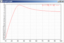
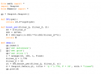
Here's some Python code and the resulting graph: [I'm having trouble with this. Hold on.]
Oops, I didn't look at the box equations too closely.
To modify, you can take the square root of the box response equation
So:
P(f)= Fn4/sqrt((Fn4-C*Fn2+A)^2+Fn2*(D*Fn2-B)^2)
A(f) = ff2/sqrt((1-ff2)^2+(ff2/Q^2))
B(f) = 1/sqrt((1-fc2)^2+(fc2/Q^2))
The response of the woofer + HP filter + LP crossover is then
20*log10(A(f)*B(f)*P(f))
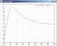
You will want to try to graph with semilog scales to get decent looking output. You notice that you get 5dB at 30 Hz rather than at the peak, that is because the formula I gave you is for dB at te hfilter frequency, not at the peak.
Looks Good!
To modify, you can take the square root of the box response equation
So:
P(f)= Fn4/sqrt((Fn4-C*Fn2+A)^2+Fn2*(D*Fn2-B)^2)
A(f) = ff2/sqrt((1-ff2)^2+(ff2/Q^2))
B(f) = 1/sqrt((1-fc2)^2+(fc2/Q^2))
The response of the woofer + HP filter + LP crossover is then
20*log10(A(f)*B(f)*P(f))
You will want to try to graph with semilog scales to get decent looking output. You notice that you get 5dB at 30 Hz rather than at the peak, that is because the formula I gave you is for dB at te hfilter frequency, not at the peak.
Looks Good!
Ron E said:Clarifying:
The boost is a 2nd order highpass filter with the equation:
A(f) = ff2/sqrt((1-ff2)^2+(ff2/Q^2))
...and yes, the Q determines the dB of peaking.
20*log10(1.778)=5dB
The shape of the curve is defined by your box design, the peaking filter and the crossover frequency. There are a lot of independent variables now, so the system can get complicated pretty fast. When applying a boost circuit, it is best to apply boost at the Fb of the vented system.
Remember, a lowpass passes the lows and cuts the highs, and a highpass passes the highs and cuts the lows. The peaking lowpass filter here cuts the lows below trhe tuning frequency and protects the vented driver below resonance. This is better known as a 6th order alignment.
The crossover is a lowpass filter - and a 2nd order lowpass has the equation:
B(f) = 1/sqrt((1-fc2)^2+(fc2/Q^2)), where :
fc2 = (F/F_crossover)^2
The response of the woofer + HP filter + LP crossover is then
20*log10(A(f)*B(f)*P(f))
I'm confused again. What is F_crossover? That's a new one. And there's a whole new part to the formula. Sorry if I'm being dense.
Are you showing how to model both the bass boost and the infrasonic filter that plate amps usually have? And if so, is F_crossover the frequency of the knee of the infrasonic (high pass) filter? Or what?
Dave Jones said:
I'm confused again. What is F_crossover? That's a new one. And there's a whole new part to the formula. Sorry if I'm being dense.
Are you showing how to model both the bass boost and the infrasonic filter that plate amps usually have? And if so, is F_crossover the frequency of the knee of the infrasonic (high pass) filter? Or what?
Light dawns over Dunderhead. Are you showing how to incorporate the effect of the sub's crossover? That must be it. F_crossover must be where I set the crossover frequency knob on the sub. Duh.
The boost graph appears to be right. I don't think I've got the crossover right though.
Questions please:
1) What is the Q in that equation? It's not the Q from the other equations is it? The crossover and boost are independent aren't they?
2) I presume "f" is "F", right?
I think when I get this figured out, I'm armed for bear.
Questions please:
B(f) = 1/sqrt((1-fc2)^2+(fc2/Q^2)), where :
fc2 = (F/F_crossover)^2
1) What is the Q in that equation? It's not the Q from the other equations is it? The crossover and boost are independent aren't they?
2) I presume "f" is "F", right?
I think when I get this figured out, I'm armed for bear.
- Status
- This old topic is closed. If you want to reopen this topic, contact a moderator using the "Report Post" button.
- Home
- Loudspeakers
- Multi-Way
- How to figure FR with bass boost?