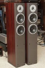
I found my Dynaudio X32s tweeters to be a little too hot for my liking. They have a very smooth response across their entire range but there is just too much of it by a guesstimate of about 3 db.
I came across a published measurement and sure enough it translated well what I was hearing.
According to an online calculator, to achieve 3 db of attenuation for an 8 ohm driver, a 2r34 and 19r39 series and parallel resistors are called for. The closest values I was able to get were 2r4 and 20r, 16 watt 2%
The tweeters DCR measured in at 5.2 ohms.
AOC1600G2R4 - Solen Electronique Inc.
AOC1600G20R - Solen Electronique Inc.
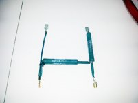
Not wanting to mess with the crossover network, I installed the L pad after the crossover, right at the tweeters terminals.
I must say the difference is not subtle, gone is the hyper detailed and at times fatiguing presentation, in it`s place, music. I regret not taking before and after measurements because it sounds like there is more at play here than a mere 3 db attenuation of the tweeter but I`m not complaining.
The speakers have become a lot more listenable with the network in place.
My question is, was this mod properly executed and is there any disadvantage to adding more passive components to an existing crossover network or should the crossover be reworked?
I came across a published measurement and sure enough it translated well what I was hearing.
According to an online calculator, to achieve 3 db of attenuation for an 8 ohm driver, a 2r34 and 19r39 series and parallel resistors are called for. The closest values I was able to get were 2r4 and 20r, 16 watt 2%
The tweeters DCR measured in at 5.2 ohms.
AOC1600G2R4 - Solen Electronique Inc.
AOC1600G20R - Solen Electronique Inc.
Not wanting to mess with the crossover network, I installed the L pad after the crossover, right at the tweeters terminals.
I must say the difference is not subtle, gone is the hyper detailed and at times fatiguing presentation, in it`s place, music. I regret not taking before and after measurements because it sounds like there is more at play here than a mere 3 db attenuation of the tweeter but I`m not complaining.
The speakers have become a lot more listenable with the network in place.
My question is, was this mod properly executed and is there any disadvantage to adding more passive components to an existing crossover network or should the crossover be reworked?
Attachments
The speakers have become a lot more listenable with the network in place.
My question is, was this mod properly executed
That should work well enough. Listen to some white noise and see if
the crossover region seems smooth.
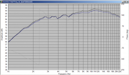
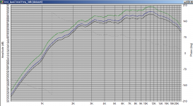
As Pete says it is the place to do it, but in answer to your question is there something more going on, then the answer is probably yes. The LPAD doesn't necessarily attenuate evenly across the frequency range. See attached an arbitrary 2nd order electrical network, with and without Lpad. I increased the spl the lpad fr curve to match as well as possible the original curve. If the attenuation was linear with frequency they would overlay completely. As you can see they don't. Black is the original response without the lpad, and blue is with the lpad added.
Note this was a sim in speaker workshop, but it's sims match reality very well.
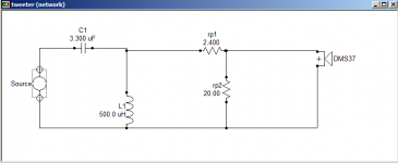
The network is shown for completeness. These were just some arbitrary values I threw in to demonstrate the non-linear effect of the attenuation.
Tony.
Note this was a sim in speaker workshop, but it's sims match reality very well.
The network is shown for completeness. These were just some arbitrary values I threw in to demonstrate the non-linear effect of the attenuation.
Tony.
Attachments
Last edited:
This small issue is easily solved
The problem is in the initial assumption of tweeter supposedly being 8 ohm which in reality is probably closer to 5-6 ohm (dcr 5.2). Lpad as is right now, pads the level 2 dB more than planned. This is likely the reason for the perceived change in sound quality.
The problem is in the initial assumption of tweeter supposedly being 8 ohm which in reality is probably closer to 5-6 ohm (dcr 5.2). Lpad as is right now, pads the level 2 dB more than planned. This is likely the reason for the perceived change in sound quality.
As Pete says it is the place to do it, but in answer to your question is there something more going on, then the answer is probably yes. The LPAD doesn't necessarily attenuate evenly across the frequency range. See attached an arbitrary 2nd order electrical network, with and without Lpad. I increased the spl the lpad fr curve to match as well as possible the original curve. If the attenuation was linear with frequency they would overlay completely. As you can see they don't. Black is the original response without the lpad, and blue is with the lpad added.
Note this was a sim in speaker workshop, but it's sims match reality very well.
The network is shown for completeness. These were just some arbitrary values I threw in to demonstrate the non-linear effect of the attenuation.
Tony.
That`s an interesting phenomenon. Do these non linearities exist in filters of greater and lesser orders too?
The problem is in the initial assumption of tweeter supposedly being 8 ohm which in reality is probably closer to 5-6 ohm (dcr 5.2). Lpad as is right now, pads the level 2 dB more than planned. This is likely the reason for the perceived change in sound quality.
You make a good point. The net acoustic attenuation does in fact seem more than just 3 db across the range as Im familiar with what +/-3db of anything sounds like.
It`s quite possible the outcome was beyond what was expected due to the assumption the tweeter impedance was indeed 8 ohms.
This mod was an experiment and the results yielded a positive effect, perhaps a little too positive. I`ll be installing a minus 2db L-pad and will report my findings.
I believe so. I think the reason is that the lpad presents a constant impedance to the crossover components, which means it's attenuation is pretty constant, close to the ideal electrical transfer function, whereas the tweeter will have a varying impedance (some more so than others) and that variation in impedance affects the transfer function of the filter.
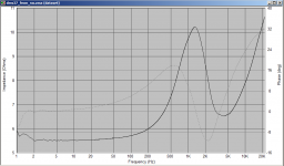
Attached is another sim and the impedance curve of the tweeter I used for the sim. I substituted the real tweeter response with a flat 92db so you can see the difference in the transfer function of the crossover with and without the lpad. Black is without the lpad. green is with the lpad, and blue is with the lpad adjusted back to roughly same level as without.
Tony.
Attachments
Something is seriously amiss.
The 2db L pad sounds substantially brighter than the 3db L pad, there is no way that is a 1db difference.
I got to get Room EQ Wizard up and running, the 3db pad seems to attenuate much more than 3db and the 2db pad attenuates too little.
In both cases, the entire spectrum seems affected and not just the tweeter levels.
Can someone verify my resistor values for the 2 and 3db pads:
2db-1r6 series,30r parallel
3db-2r4 series,20r parallel
Attachments
Last edited:
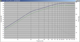
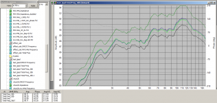
I just did a sim with my Morel DMS37 data. This time I just used a single 4.7uF cap for the crossover. With this tweeter your lpads are pretty close to 2db and 3db attenuation.
Green is just the 4.7uF cap no lpad
Black is the 3db lpad
Blue is the 2db lpad.
It seems that there really is only 1db of difference between the two. It may be that you are very sensitive to imbalance in the upper frequency ranges and 1db seems like a lot more than in lower frequency ranges (I know I am very sensitive to tweeter levels).
however I just scaled up the -3db measurement by 1db and in places it is close but in others there is slightly more than 1db of difference. In the second attachment there is 0.24db difference at approx 9.4k The yellow curve is the -3db curve increased by 1db.
Tony.
Attachments
Perhaps if the crossover schematic could be supplied, as suggested by Lojzek, the effect of the attenuator pad on the listening experience could be better understood. Certainly a 1dB difference is audible and the resistor values are accurate for the pads. Crossover circuits such as the parallel first and third order variety do not provide effective damping below the crossover frequency for the high frequency leg and the // resistor in the L pad can provide some damping which will increase proportionally with higher levels of attenuation.
- Status
- This old topic is closed. If you want to reopen this topic, contact a moderator using the "Report Post" button.
- Home
- Loudspeakers
- Multi-Way
- Attenuating Dynaudio tweeter