Hello Everyone.
I have been a long time lurker @ diyaudio, I have admired the knowledge and work of many people here. I have finally decided to take the plunge and design my own speaker.
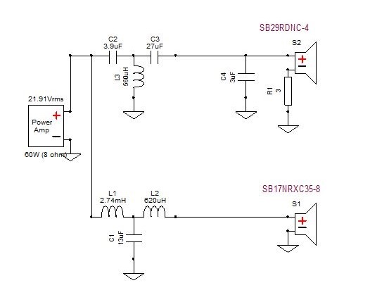
I have decided to use SB17NRXC35-8 and SB29RDNC as they have very good reviews on the forum and some commercial kits based these drivers. meaning they go well together and offer good value.
This is my first time designing a crossover.
I am sure I have made some pretty dumb mistakes, Please take a look and let me know how this design can be improved.
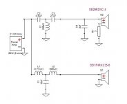
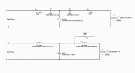
The crossover is designed using Xsim3D.
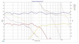
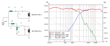
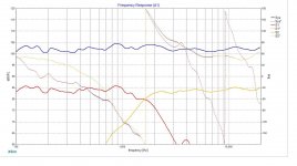
the design is +/-2db I am hoping to achieve +-3db in real world.
I have taken the Frequency response from manufacturers site pictures and converted to frd with spl trace program in vituixcad.
The design is compensated for baffle step diffraction generated by vituixcad.
Drivers will be physically aligned for time delay /Phase.
Baffle will be 9w x 18h x 12d enclosure using 0.75 mdf. 2x10 inch ported bass reflex box. (Calculated from vituix cad)
Thanks to @bwaslo and @kimmosto for their wonderful software.
Both great in their own right.
I have been a long time lurker @ diyaudio, I have admired the knowledge and work of many people here. I have finally decided to take the plunge and design my own speaker.
I have decided to use SB17NRXC35-8 and SB29RDNC as they have very good reviews on the forum and some commercial kits based these drivers. meaning they go well together and offer good value.
This is my first time designing a crossover.
I am sure I have made some pretty dumb mistakes, Please take a look and let me know how this design can be improved.
The crossover is designed using Xsim3D.
the design is +/-2db I am hoping to achieve +-3db in real world.
I have taken the Frequency response from manufacturers site pictures and converted to frd with spl trace program in vituixcad.
The design is compensated for baffle step diffraction generated by vituixcad.
Drivers will be physically aligned for time delay /Phase.
Baffle will be 9w x 18h x 12d enclosure using 0.75 mdf. 2x10 inch ported bass reflex box. (Calculated from vituix cad)
Thanks to @bwaslo and @kimmosto for their wonderful software.
Both great in their own right.
Attachments
-
 sb17nrxc35-8-sb29rdnc-4-crossover.jpg23.9 KB · Views: 1,457
 -
 sb17nrxc35-8-sb29rdnc-4-Frequency-response.jpg192.1 KB · Views: 788
 -
 sb17nrxc35-8-sb29rdnc-4-Frequency-response-inverted.jpg198.2 KB · Views: 699
 -
 sb17nrxc35-8-sb29rdnc-4-Impedence.jpg201 KB · Views: 671
 -
 sb17nrxc35-8-sb29rdnc-4-baffle-placement.jpg21.2 KB · Views: 752
Last edited:
Looks like a very good place to start. But it would be better if you took the impedance, frequency response, and SPL measurements from the drivers you're going to use rather than factory cut sheets. At first, I'd build the crossovers outside of the speaker cabinets. You might need to make some adjustments on the sound and it's much easier swapping components with the crossovers external. Some people even prefer external crossovers as they feel there's less interference from speaker magnets and vibration.
Last edited:
SUGGEST: Simulate 2-3 different crossovers before you purchase crossover parts.
a) different L-pad constructions for the tweeter....tweeter directly connected to ground.
b) a lower crossover frequency ~1700-1800Hz to study if this improves the polar response and on-axis performance. --The midrange starts cone breakup at 3500Hz, and a lower Xover might better attenuate the distortion.
c) to reduce the tweeter resonance impedance, add and LRC filter and study the value
GREAT CHOICE OF DRIVERS: You have selected two of the best modest cost drivers for your first build.
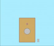
QUESTION: Do you plan to construct a physically stepped front baffle for time alignment??
QUESTION: Will you mount the tweeter slightly off-center on the baffle to spread the diffraction energy? OR will the stepped front baffle cuts cancel an off-center tweeter?
QUESTION: Do you plan any edge bevels or rounds to reduce diffraction distortion?
QUESTION: Do you have friends with basic measurement equipment? You can read about $20 mic and free software.
---
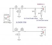
In this tweeter L-Pad example, the goal it to maintain the Re of the tweeter(~3.7ohms) around the crossover frequency, and to attenuate the tweeter SPL, and to increase the resistance seen at the amplifier.
If a larger increase in impedance @amplifier is necessary, a combination of a modest attenuation L-Pad plus a modest series resistor between the amplifier and the tweeter crossover is often used.
a) different L-pad constructions for the tweeter....tweeter directly connected to ground.
b) a lower crossover frequency ~1700-1800Hz to study if this improves the polar response and on-axis performance. --The midrange starts cone breakup at 3500Hz, and a lower Xover might better attenuate the distortion.
c) to reduce the tweeter resonance impedance, add and LRC filter and study the value
GREAT CHOICE OF DRIVERS: You have selected two of the best modest cost drivers for your first build.
QUESTION: Do you plan to construct a physically stepped front baffle for time alignment??
QUESTION: Will you mount the tweeter slightly off-center on the baffle to spread the diffraction energy? OR will the stepped front baffle cuts cancel an off-center tweeter?
QUESTION: Do you plan any edge bevels or rounds to reduce diffraction distortion?
QUESTION: Do you have friends with basic measurement equipment? You can read about $20 mic and free software.
---
In this tweeter L-Pad example, the goal it to maintain the Re of the tweeter(~3.7ohms) around the crossover frequency, and to attenuate the tweeter SPL, and to increase the resistance seen at the amplifier.
If a larger increase in impedance @amplifier is necessary, a combination of a modest attenuation L-Pad plus a modest series resistor between the amplifier and the tweeter crossover is often used.
Attachments
Looks like a very good place to start. But it would be better if you took the impedance, frequency response, and SPL measurements from the drivers you're going to use rather than factory cut sheets. At first, I'd build the crossovers outside of the speaker cabinets. You might need to make some adjustments on the sound and it's much easier swapping components with the crossovers external. Some people even prefer external crossovers as they feel there's less interference from speaker magnets and vibration.
SB drivers are not readily available in my area, It is a 30 day wait ,so I just did a simulation to make sure that I have a good starting point before I ordered them. I do plan to measure the response and make necessary tweaks.
I tried using resitors, it it was dissipating way too much heat. 18 ohm +9 ohm each dissipating 40 watts, I could not find parts.SUGGEST: Simulate 2-3 different crossovers before you purchase crossover parts.
a) different L-pad constructions for the tweeter....tweeter directly connected to ground.
My current crossover is at 1650 range. should I go higher?b) a lower crossover frequency ~1700-1800Hz to study if this improves the polar response and on-axis performance. --The midrange starts cone breakup at 3500Hz, and a lower Xover might better attenuate the distortion.
You lost me there. You mean to reduce the impedence at Fs ?c) to reduce the tweeter resonance impedance, add and LRC filter and study the value
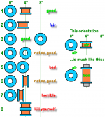
I want to construct a physically stepped baffle , similar to this one.GREAT CHOICE OF DRIVERS: You have selected two of the best modest cost drivers for your first build.
QUESTION: Do you plan to construct a physically stepped front baffle for time alignment??
QUESTION: Will you mount the tweeter slightly off-center on the baffle to spread the diffraction energy? OR will the stepped front baffle cuts cancel an off-center tweeter?
QUESTION: Do you plan any edge bevels or rounds to reduce diffraction distortion?
QUESTION: Do you have friends with basic measurement equipment? You can read about $20 mic and free software.
---
SBAcoustics-61-NRXC
I plan to round off the edges with a 6mm rounded edge
Tweeter will be mounted center of the box,
I do have a $20 mic that I use. But I am not confident on my measurement skills.
I do however have a friend who has DATS v2 and omnimic package and has the skills and location to do the measurement. He will help me do the measurements.
In this tweeter L-Pad example, the goal it to maintain the Re of the tweeter(~3.7ohms) around the crossover frequency, and to attenuate the tweeter SPL, and to increase the resistance seen at the amplifier.
If a larger increase in impedance @amplifier is necessary, a combination of a modest attenuation L-Pad plus a modest series resistor between the amplifier and the tweeter crossover is often used.
Your design has the tweeter absolutely flat. With the same values my crossover goes to 1500 from 1650. I guess that is the difference between measured and simulated FRDs.
Let me try some L-pad changes and see if I can achieve similar results.
Can we add it to the negative side, so that there are no resistors in signal path? In theory a series resistor before or after the load will sum up to the same value. Xsim also shows that. will there be a difference in actual measurements?.
This is not a bad idea:
You really must lose the 3uF capacitor though. It wrecks impedance at high frequency. Short circuit! Crossover is unnecessarily low too, and looks more of an 8 ohm circuit on the tweeter. With 4 ohms, the cap gets bigger, and the coil smaller, so 6.8uF and 0.15mH is more reasonable.
But third order at 2.2-2.7kHz is a good idea, because most 6" drivers have some bad breakup around 5kHz. I'm not convinced tweeter level is right here. I'd expect more attenuation resistance in front of the circuit. That 4 ohm tweeter is loud, isn't it?
I'd play with the circuits below on your simulator. Even Troels' one ought to be easy enough to replicate. Setting the tweeter back 2cms solves a lot of phase problems with 6".
Some help here:
SB Acoustics :: Eka Kit
SB Acoustics :: Arya Kit
Notice SB now fit a 5kHz notch in the Eka MkII.
Attachments
You really must lose the 3uF capacitor though. It wrecks impedance at high frequency. Short circuit! Crossover is unnecessarily low too, and looks more of an 8 ohm circuit on the tweeter. With 4 ohms, the cap gets bigger, and the coil smaller, so 6.8uF and 0.15mH is more reasonable.
But third order at 2.2-2.7kHz is a good idea, because most 6" drivers have some bad breakup around 5kHz. I'm not convinced tweeter level is right here. I'd expect more attenuation resistance in front of the circuit. That 4 ohm tweeter is loud, isn't it?
I'd play with the circuits below on your simulator. Even Troels' one ought to be easy enough to replicate. Setting the tweeter back 2cms solves a lot of phase problems with 6".
Some help here:
SB Acoustics :: Eka Kit
SB Acoustics :: Arya Kit
Notice SB now fit a 5kHz notch in the Eka MkII.
the woofer breakup starts early for this driver and starts around 3.5 to 4k, so trying to crossover early.
I have tried ideas Both the ideas presented above. and arrived at the new crossover.
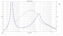
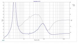
The overall impedence at the tweeter crossover is around 8 ohm.
Let me know if I am on the right path with this change.
Attachments
Last edited:
You are reinventing the wheel, IMO. It's been done before by people with far more experience than you.
Stick to an established design. I can't imagine why anyone would need 20W resistors in a tweeter filter. A tweeter rarely goes above 10W continuous overall. Higher figures are momentary surges.
2.2 KHz crossover is quite acceptable with high order filters too.
6" SB17NRXC35-8 :: SB Acoustics
I can see why SB added a 5kHz notch though with a third order. The alternative is Troels' 4th order bass.
If you have an accepatble design for one section of a filter, you only have to match the other one to it acoustically, and it all works out.
Last edited:
My understanding is that Tweeter gets 60watts (Max power accepted) power 10-12 watts is used and the rest is dissipated as heat by the resistors.
The tweeter is much sensitive than the woofer, and also the woofer needed to be padded down for compensating baffle loss. so overall the tweeter sensitivity has to be padded down from 94db to 85 db, Hence the heavy use of resistors.
Please let me know of there are other ways to do this.
The tweeter is much sensitive than the woofer, and also the woofer needed to be padded down for compensating baffle loss. so overall the tweeter sensitivity has to be padded down from 94db to 85 db, Hence the heavy use of resistors.
Please let me know of there are other ways to do this.
You already have had a lot of good advice.
Depending on your data and where you traced it from you have a possible solution. If you built it, it would provide you with a baseline to work from, if fact it may sound good to your ears, and that is a fundamental to enjoying your creation.
As the others have suggested taking a real measurement with the drivers in their proposed cabinet will allow you to get better info for the simulator software you are using. As the drivers are some days away, and you do not want to waste money on a wrong selection of components simulation was the best approach. Taking advice from system7 by looking at the SB kit data is a good idea. However, I think the smaller design uses the 4 ohm version of your driver, so not able to read across values directly. As pointed out it seems they now use a 5K Hz notch with their chosen 3KHz crossover in the Mk2 design. Which would indicate that you can use that 4 ohm driver up to 3KHz before crossing over to the tweeter. Maybe you could do the same with yours and add a 5Khz notch if needed, you will need different values as yours is the 8 ohm driver. Again the simulation will help you here
As per the smaller SB kit plans crossing over a tweeter at 3 KHz can give the tweeter and easier ride and should help lower tweeter distortion. Some tweeters can handle 1.7K-2.0Khz crossover with your chosen 3rd order filter, others require 4th order to be safe and protect the tweeter form too much excursion. All these factors are part of the compromises in a loudspeaker design.
If you build your current design and find it is not to your liking, tweaking the crossover will provide a workable solution. The inductors are quite large values and could be unwound easily to give you less inductance. You may find you do not need 4-6dB of baffle step.
You already have had a lot of good advice.
Depending on your data and where you traced it from you have a possible solution. If you built it, it would provide you with a baseline to work from, if fact it may sound good to your ears, and that is a fundamental to enjoying your creation.
As the others have suggested taking a real measurement with the drivers in their proposed cabinet will allow you to get better info for the simulator software you are using. As the drivers are some days away, and you do not want to waste money on a wrong selection of components simulation was the best approach. Taking advice from system7 by looking at the SB kit data is a good idea. However, I think the smaller design uses the 4 ohm version of your driver, so not able to read across values directly. As pointed out it seems they now use a 5K Hz notch with their chosen 3KHz crossover in the Mk2 design. Which would indicate that you can use that 4 ohm driver up to 3KHz before crossing over to the tweeter. Maybe you could do the same with yours and add a 5Khz notch if needed, you will need different values as yours is the 8 ohm driver. Again the simulation will help you here
As per the smaller SB kit plans crossing over a tweeter at 3 KHz can give the tweeter and easier ride and should help lower tweeter distortion. Some tweeters can handle 1.7K-2.0Khz crossover with your chosen 3rd order filter, others require 4th order to be safe and protect the tweeter form too much excursion. All these factors are part of the compromises in a loudspeaker design.
If you build your current design and find it is not to your liking, tweaking the crossover will provide a workable solution. The inductors are quite large values and could be unwound easily to give you less inductance. You may find you do not need 4-6dB of baffle step.
Yes I agree, I got some good advise and 3 different versions of crossover with different crossover points.
I will try to reduce baffle step compensation to 3-4 db instead of full compensation. and look at how it performs.
I am ordering parts from all the crossover designs, as there are lot of repeated parts, will only add about 10-20$ to overall bill.
I will try different versions to see which works.
I have found that a 1700-1800Hz crossover is a good range. When I used your Xover circuit with my flat baffle measured data the crossover point was closer to 2kHz, which seemed higher than optimal.
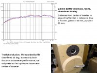
The SB29RDC tweeter has Fs ~ 600-620Hz, and sometimes this can combine with edge diffraction effects to produce a noticable SPL bump... just sometimes, and only when no parallel-shunt L-pad resistor is used. I usually simulate a resonant RLC filter to observe the SPL bump, but never use it with the low Le SB29RDC tweeter because the circuit affects a wide SPL range.
Based on Troels measurements, a curved and beveled-cut baffle-step seems worth the effort.
Most designers wait to purchase the speakers and crossover parts from the same vendor to combine shipping cost.
Measurements are the REAL education course! You are lucky to have a friend who has DATS plus measurement experience.
Attachments
I have found that a 1700-1800Hz crossover is a good range. When I used your Xover circuit with my flat baffle measured data the crossover point was closer to 2kHz, which seemed higher than optimal.
The SB29RDC tweeter has Fs ~ 600-620Hz, and sometimes this can combine with edge diffraction effects to produce a noticable SPL bump... just sometimes, and only when no parallel-shunt L-pad resistor is used. I usually simulate a resonant RLC filter to observe the SPL bump, but never use it with the low Le SB29RDC tweeter because the circuit affects a wide SPL range.
I will try the RLC filter, I will start with online calculator values and go from there.
Based on Troels measurements, a curved and beveled-cut baffle-step seems worth the effort.
I plan to follow the same design as Troels. only with a slightly larger baffle.
Most designers wait to purchase the speakers and crossover parts from the same vendor to combine shipping cost.
SB drivers are the only things unavailable and have to be special ordered. Crossover parts are easily available and at reasonable prices. Dont have to wait if I miss some parts.
Measurements are the REAL education course! You are lucky to have a friend who has DATS plus measurement experience.
Yes, really Lucky. I do plan to learn how to measure when I get the drivers.
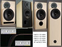
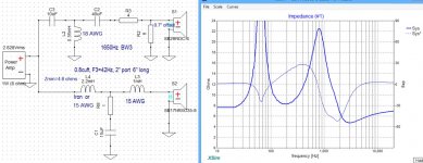
Ported SB17NRXC35-8
-----------
0.6ft^3 = F3 =48Hz
0.7ft^3 = F3 =45Hz
0.8ft^3 = F3 =42Hz
1.0ft^3 = F3 =38Hz
43“ tall MLTL~35Hz
0.6-0.7 Cu ft works for me. I will just replicate Troels' build with some minor aesthetic changes to my taste.
SUGGEST: Simulate Tweeter LR2(inverted) + Midrange LR2 crossover circuits with your zero-offset time-stepped baffle. Study the modest phase shift. Study the effects of the 3.5kHz SB17NRXC35 paper midrange cone breakup with a shallow LR2 slope.
Troels accepts the edge diffraction from a time-step baffle because he favors the low phase shift with time-aligned (-)LR2_tweet (+)LR2_midrange crossover circuits. Supporters of LR2/LR2 crossover circuits will sometimes add an LRC notch filter to attenuate the 3.5kHz cone breakup.
---
The polypropylene cone SB17MFC35 has less cone breakup distortion than the paper SB17NRXC35, and could simplify low distortion LR2/LR2 crossovers.
======
On a flat baffle, the polypropylene cone SB17MFC35 can support a 2kHz BW3/BW3 crossover circuit to the 2" motor diameter SB26STCN-4 tweeter for reduced acoustic interference at the listener. The improved high frequency polar pattern is desirable for a 3-way.... just add a 12" woofer like the SB34NRX75.
SUGGEST: Simulate Tweeter LR2(inverted) + Midrange LR2 crossover circuits with your zero-offset time-stepped baffle. Study the modest phase shift. Study the effects of the 3.5kHz SB17NRXC35 paper midrange cone breakup with a shallow LR2 slope.
Troels accepts the edge diffraction from a time-step baffle because he favors the low phase shift with time-aligned (-)LR2_tweet (+)LR2_midrange crossover circuits. Supporters of LR2/LR2 crossover circuits will sometimes add an LRC notch filter to attenuate the 3.5kHz cone breakup.
---
The polypropylene cone SB17MFC35 has less cone breakup distortion than the paper SB17NRXC35, and could simplify low distortion LR2/LR2 crossovers.
======
On a flat baffle, the polypropylene cone SB17MFC35 can support a 2kHz BW3/BW3 crossover circuit to the 2" motor diameter SB26STCN-4 tweeter for reduced acoustic interference at the listener. The improved high frequency polar pattern is desirable for a 3-way.... just add a 12" woofer like the SB34NRX75.
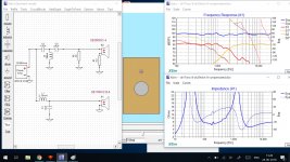
I have tried LR2 on on tweeter (inverted) and Woofer, But could not get an acceptable result.
I have done a 2nd order on Woofer and 3rd order on tweeter. It works, However is woofer 16 db down at 3.5-4k, will it be audible? (attached)
I also replaced my simulated woofer frd with actual ones from troels' in different versions of the crossover and got very similar results. This is very encouraging.
I dont plan for a 3way, Dont want to bite off more than I can chew.
Attachments
- Status
- This old topic is closed. If you want to reopen this topic, contact a moderator using the "Report Post" button.
- Home
- Loudspeakers
- Multi-Way
- crossover design sb17nrx ,sb29rdnc. Will this work?