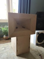
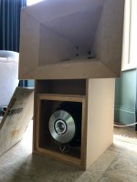
I have started a Synergy build using the Celestion TF0410MR as the midrange driver. The plan is to have 2x per horn but at the moment I've just got one attached for testing, firing through 2x 0.75" ports placed 3.5" down the horn. The horn is constructed using 12mm MDF and uses Bill Waslo's spreadsheet with a 65 x 45 degree coverage.
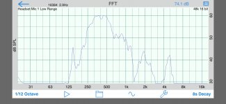
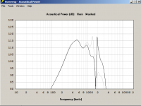
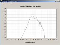
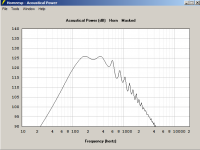
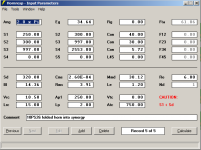
I have done a quick frequency response measurement indoors and see a sudden drop-off way before the desired 1kHz crossover frequency, starting at around 500Hz. You can see this in the attached screen grab. Is this typical? It seems like it might be based on some other forum posts I have seen. Would love some advice on what to expect! Thanks
I have done a quick frequency response measurement indoors and see a sudden drop-off way before the desired 1kHz crossover frequency, starting at around 500Hz. You can see this in the attached screen grab. Is this typical? It seems like it might be based on some other forum posts I have seen. Would love some advice on what to expect! Thanks
Attachments
Not what you want it to look like, no. Your cancellation notch is in about the right place, so I'd guess that maybe your port lengths are too long (try frustrums?) or the port sizes are wrong. You could also try filling up some of the volume between cone and the outside horn wall (the "front volume" in Horn Response). You should probably put together a quick Horn Response model (of just the midrange -- use "offset horn", per the Synergy calc spreadsheet) and see what it says. If it shows a better response, try playing with ports sizes, length, and front volume to see what makes it go similar to what you are seeing -- then do t he opposite!
Mounted on a horn it's a 4th order band-pass [BP] alignment, so for a given rear chamber volume [Vrc] and vent system, reducing its front chamber volume [Vtc] increases HF output as proven by the 'hemi-head' compression chamber of the DSL Synergys I've seen loaded with purportedly this driver or one with [near] identical specs:
Drat! There use to be a picture of a partially assembled one on the net that clearly shows this, but can't find it in a quick search. Regardless, I imagine this is already well documented on one or more of the DIYer's threads and of course can be simmed in at least AkAbak, Hornresp.
GM
Drat! There use to be a picture of a partially assembled one on the net that clearly shows this, but can't find it in a quick search. Regardless, I imagine this is already well documented on one or more of the DIYer's threads and of course can be simmed in at least AkAbak, Hornresp.
GM
It shouldn't look like that.
I'd check the following:
1) How deep are the midrange taps?
2) Are you sure the chamber is sealed? It must be absolutely 110% airtight. I use a strip of mortite along the midrange to be sure.
3) Possibly a defective driver
4) Do you have a filter on in the chain? I use a miniDSP and sometimes I find that I'm adjusting the wrong channel. I've nearly blown up tweeters this way :O
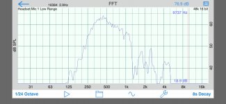
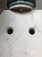
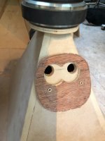
I added a gasket cut out of the thin underlay you can get for laminate flooring and this made quite a big difference to the response (attached). I guess the next thing I will do is modify the port holes to look more like the frustums on the other DIY synergy projects, as at the moment the sides of the holes are only smoothed with a round-over router bit (also attached).
Attachments
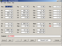
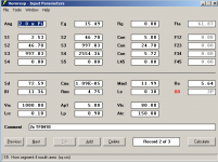
Thanks for the tips. I am wondering how to model the driver in hornresp, given that it already has a closed back?
http://www.diyaudio.com/forums/multi-way/314086-2-unity-horn-300hz-noob-questions.html#post5229909 should help
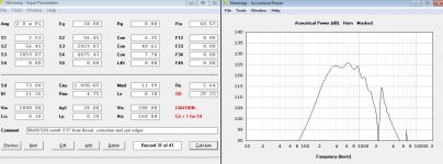
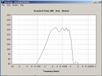
Thanks, used this for the TF0410MR Thiele Small params and can see now from the Hornresp model that my ports are too big. My total port area (4 ports, 2 drivers) is 12.56cm2 which causes the response to drop off from 1kHz (black line on the attached plot). If I decrease to 5cm2 the response is extended and starts to drop off at around 1.5Khz (grey line on the attached plot).
I'm going to fill the holes and try again with a 12mm drill bit to start with (4x 12mm is 4.2cm2 area). Interestingly if I thin the port walls (currently 12mm) with a frustum then Hornresp shows a drop at around 1kHz and a peak just above 2kHz which is not desirable. Therefore I think I will avoid the frustum but instead gently round the corners with a file.
Attachments
Last edited:

Am watching this thread as I have a bunch of the celestions waiting for some horns to be built.
I have done a few sims but not spent too much time on them as I'm still sorting out my table saw.
Here's a shot of a 50x50 horn with a 520Hz cutoff. I think I used the thread linked above for the driver specs.
I have done a few sims but not spent too much time on them as I'm still sorting out my table saw.
Here's a shot of a 50x50 horn with a 520Hz cutoff. I think I used the thread linked above for the driver specs.
Attachments
The steep "drop" (or notch) centered near 2kHz in both plots is the reflection notch -- nothing you do to the ports will move or get rid of that. But reducing the front volume and, it appears, reducing the port area will pull it up below that point and can help keep it down just above. (That sharp peak in the plot probably won't really happen like that, but you still want to keep the energy down in that area).
What is interesting is that if I simulate a 6mm spacer in between the driver and the horn wall (~50cm3 per driver), thereby increasing the front volume, the response looks a lot better than the one with the lower volume.
FYI I calculated the driver's front volume as 33.3cm3 and didn't include the port volume (around 0.8cm2 per port right now). If I add the port volume it doesn't have much impact though.
Should I go with this approach, with the 6mm spacer and a steep drop-off after 1.2kHz? It makes life a lot easier not having to route a ring in the horn wall to avoid the driver impacting at Xmax
I also tried moving the driver up and down the horn but it did not really change the response (this calculation was very easy thanks to Bill's spreadsheet).
Attachments
Should I go with this approach, with the 6mm spacer and a steep drop-off after 1.2kHz? It makes life a lot easier not having to route a ring in the horn wall to avoid the driver impacting at Xmax
t).
the nice steep slope seems ideal until you think about the XO to the CD - it will need a complementary, steep slope, which of course is not hard to do with DSP.
Of course if you have reservations about using brick wall filters, (e.g. don't like the latency) then you should consider tweaking bandpass chamber and port parameters for the most gradual slope you can achieve. I've done this exercise a few times, making the reflection notch shrink to a small glitch in the middle of the gradual roll off response transition. When you have such a response you can equalize it to match an LR8 acoustic slope with IIR filters and the XO will be as high as or nearly as high as with the brick wall response, and you will have plenty of rejection for the HF response artifacts that get through the acoustic low pass filtering.
The steep response that you have is so steep that it may be hard to match to the CD you are crossing over to. When you add filtering to soften it up or for additional attenuation above the dropoff, you will likely pull the XO point lower.
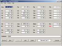
Here is the latest attempt, aiming for a flat passband and to get up towards 2kHz.
I don't think I can do much about the bottom end extension as it is a sealed back mid.
I don't think I can do much about the bottom end extension as it is a sealed back mid.
Attachments
quick advice
Vrc is unrealistically large try about 2 cc, not much difference but more accurate
S1 doesn't match CD exit. change to 5 cm2, again not much difference
Ap is too small, check particle velocity in port, should be less than 17 m/s at LF peak
L12 assumes sound bounces off apex of horn for reflection null when in fact it bounces off phase plug typically 3 cm or so deep inside the CD. Increase L12 to match CD.
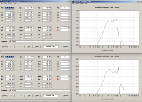
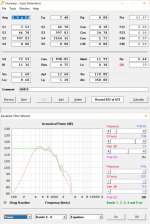
Response shape is still too steep except for brick wall filter XO. Look at attached for alternative tuning. Green trace is 1250 Hz LR6 acoustic target. Grey is raw response. Red is response EQed to match target response using available PEQs in HR.
The ripples in the raw response are, I believe, due to mouth reflections which could be reduced with round overs instead of a secondary flare. Also, state of DIY art, is 3D printed throat matching exit angle of CD.
Good luck.
Vrc is unrealistically large try about 2 cc, not much difference but more accurate
S1 doesn't match CD exit. change to 5 cm2, again not much difference
Ap is too small, check particle velocity in port, should be less than 17 m/s at LF peak
L12 assumes sound bounces off apex of horn for reflection null when in fact it bounces off phase plug typically 3 cm or so deep inside the CD. Increase L12 to match CD.
Response shape is still too steep except for brick wall filter XO. Look at attached for alternative tuning. Green trace is 1250 Hz LR6 acoustic target. Grey is raw response. Red is response EQed to match target response using available PEQs in HR.
The ripples in the raw response are, I believe, due to mouth reflections which could be reduced with round overs instead of a secondary flare. Also, state of DIY art, is 3D printed throat matching exit angle of CD.
Good luck.
Attachments
Depending on what parameters are being used for the driver, I think the huge Vrc is the right way to go. This is a sealed back driver, changing the back volume isn't going to do anything in the least since it's blocked from the back of the cone. The compliance Cms from the driver measurements already includes all the volume restriction that can ever happen, so don't want a Vrc entry that can affect the operational compliance.
I think I am getting somewhere now, thanks to all the tips. I have done the following:
- Implemented most of the suggested tweaks from nc535 in the simulation
- Moved the taps up towards the apex, now 2.5" down rather than 3.3"
- Changed the tap diameter to 20mm
- Got rid of the routed ring around the edge of the driver, since I can see that at xmax of 1mm it is not necessary
- Changed tap hole depth back to 12mm
- Added a 8mm layer of plywood with a 38mm diameter hole cut out over each tap. By playing with different sized holes the volume of the front chamber can be fairly precisely predicted. Much better than when routing out the frustum from the horn wall. Of course this only works well because these drivers perform better with some volume in front.
Pics attached... seems to be looking good now?
Attachments
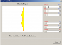
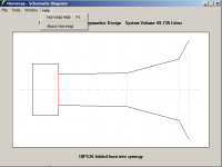
I started integrating the bass, using a single B&C 10PS26 per side. The modelling showed this would work better with a long port length and the only way I could see of physically getting this integrated was by doing something like the Danley Jericho, where there is a secondary horn for the bass driver that joins the main horn close to the exit. I was not fully sure about how to model it in Hornresp and just did it as a conical horn with the driver at the apex (not offset driver) and 3 sections. So If you look at the schematic attached, the junction with the main horn is just right of the centre of the picture. I figured that once I had it looking ok in hornresp I would make a prototype and see how it turned out.
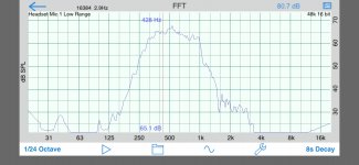
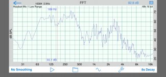
In actual fact the bass extension is much better, but I am measuring this indoors. There is a null at around 160Hz that moved from 190Hz when I moved the speaker in the room, so I am guessing it is a boundary cancellation? I still need to get this outside to measure it properly.
As others have noted, the sealing is really important. When I did not have it properly sealed everywhere there were some strange noises.
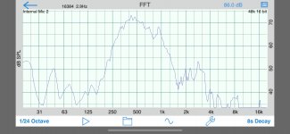
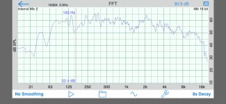
I've also attached the response of the full 3-way, again measure indoors. I have not really spent much time on tuning this yet, but it sounds awesome already and is very loud even with only one midrange driver connected (I will have 2 in the final version).
In actual fact the bass extension is much better, but I am measuring this indoors. There is a null at around 160Hz that moved from 190Hz when I moved the speaker in the room, so I am guessing it is a boundary cancellation? I still need to get this outside to measure it properly.
As others have noted, the sealing is really important. When I did not have it properly sealed everywhere there were some strange noises.
I've also attached the response of the full 3-way, again measure indoors. I have not really spent much time on tuning this yet, but it sounds awesome already and is very loud even with only one midrange driver connected (I will have 2 in the final version).
Attachments
-
 Screen Shot 2018-07-28 at 19.50.20.png169.8 KB · Views: 311
 -
 Screen Shot 2018-07-28 at 19.50.10.png120 KB · Views: 320
 -
 IMG_1495.jpg321.6 KB · Views: 371
 -
 IMG_1496.jpg299.3 KB · Views: 456
 -
 IMG_1493.jpg454 KB · Views: 480
 -
 IMG_1494.jpg448.8 KB · Views: 539
 -
 Screen Shot 2018-07-28 at 19.50.43.png163.6 KB · Views: 302
- Status
- This old topic is closed. If you want to reopen this topic, contact a moderator using the "Report Post" button.
- Home
- Loudspeakers
- Multi-Way
- Synergy build with TF0410MR mids