Hi all-
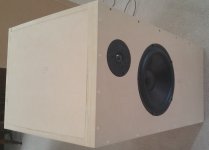
I have designed and built a pair of quarter-wave 10:1 tapered transmission line speakers with 10” woofers and dome tweeters. I plan on bi-amping them.
I have gotten unexpected results when stuffing the speakers with Acousta-Stuf Polyfill and watching the woofer impedance curves change. The results so far seem to show that much more than the oft suggested 0.5 or 0.75 lbs per cubic foot will be needed. The speakers are ~4 cubic feet each.
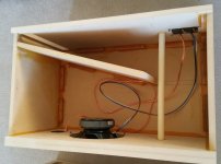
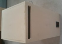
One of the speakers is shown in the first 3 images.
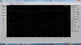
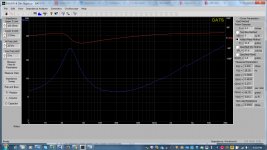
After breaking the woofers in I measured their impedance using DATS (Dayton Audio Test System). Below in the forth image is the free-air impedance magnitude (blue) and phase (red) versus frequency curves for one of the Parts Express DSA270-8 10” woofer: The resonant peak is approx. 28.3Hz.
I then mounted the 10” woofer in the cabinet w/o any stuffing, closed the open side of the cabinet, and measured the impedance curves again. See the fifth image.
As expected, the single impedance peak for the woofer in free air is replaced by 2 peaks on either side of the free air peak.
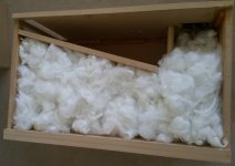
Next- I stuffed the cabinet with 2.5lbs of Acousta-Stuf Polyfill from Parts Express. I then remeasured the impedance. See the sixth image.
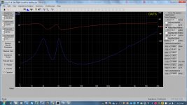
The change was small. I then added my remaining 2.5lbs of Polyfill to the same speaker and remeasured the impedance. See the seventh and eight images.
As you can see the magnitude of the peaks are reduced and they are starting to become 1 peak. It seems to get rid of the dual peaks will take a huge amount of Pollifil- maybe 10lbs. Any ideal what the issue is? Note that the impedance curves are taken using a small signal setup. Will the impedance curves change if done at more realistic power levels?
Any help is appreciated.
I have designed and built a pair of quarter-wave 10:1 tapered transmission line speakers with 10” woofers and dome tweeters. I plan on bi-amping them.
I have gotten unexpected results when stuffing the speakers with Acousta-Stuf Polyfill and watching the woofer impedance curves change. The results so far seem to show that much more than the oft suggested 0.5 or 0.75 lbs per cubic foot will be needed. The speakers are ~4 cubic feet each.
One of the speakers is shown in the first 3 images.
After breaking the woofers in I measured their impedance using DATS (Dayton Audio Test System). Below in the forth image is the free-air impedance magnitude (blue) and phase (red) versus frequency curves for one of the Parts Express DSA270-8 10” woofer: The resonant peak is approx. 28.3Hz.
I then mounted the 10” woofer in the cabinet w/o any stuffing, closed the open side of the cabinet, and measured the impedance curves again. See the fifth image.
As expected, the single impedance peak for the woofer in free air is replaced by 2 peaks on either side of the free air peak.
Next- I stuffed the cabinet with 2.5lbs of Acousta-Stuf Polyfill from Parts Express. I then remeasured the impedance. See the sixth image.
The change was small. I then added my remaining 2.5lbs of Polyfill to the same speaker and remeasured the impedance. See the seventh and eight images.
As you can see the magnitude of the peaks are reduced and they are starting to become 1 peak. It seems to get rid of the dual peaks will take a huge amount of Pollifil- maybe 10lbs. Any ideal what the issue is? Note that the impedance curves are taken using a small signal setup. Will the impedance curves change if done at more realistic power levels?
Any help is appreciated.
Attachments
-
 Speaker front.jpg204.2 KB · Views: 1,253
 -
 Speaker with 5lbs stuffing.jpg360.3 KB · Views: 631
 -
 Speaker w 5lbs stuffing.jpg273.2 KB · Views: 679
 -
 Speaker with 2_5lbs stuffing.jpg366.4 KB · Views: 602
 -
 Speaker no stuffing.jpg368.5 KB · Views: 1,275
 -
 Woofer free air impedance.jpg370.1 KB · Views: 1,270
 -
 Speaker side.jpg268.1 KB · Views: 1,238
 -
 Speaker back.jpg178.5 KB · Views: 1,213
If you get to just 1 peak you are really close to having an aperiodic line with very little bass reinforcement.
The 2nd impedance curve shows that you have wiped out the bumps just above 100 and just below 200. These are indications and if you want bass reinforcement, but little ripple that is the goal.
Also, it looks like you have not adequately teased the acoustastuff. It should look uniform. it is a lot of work… for 2.5 pounds i would expect hours of work.
This is 40g. It took at least 20 min to tease to this point.
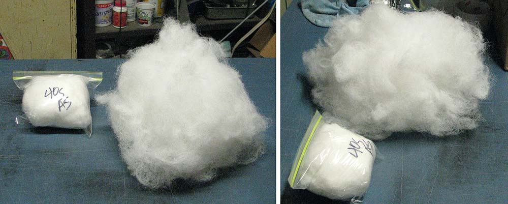
I also would not have the acoustastuff near as dense around the back of the driver.
dave
The 2nd impedance curve shows that you have wiped out the bumps just above 100 and just below 200. These are indications and if you want bass reinforcement, but little ripple that is the goal.
Also, it looks like you have not adequately teased the acoustastuff. It should look uniform. it is a lot of work… for 2.5 pounds i would expect hours of work.
This is 40g. It took at least 20 min to tease to this point.
I also would not have the acoustastuff near as dense around the back of the driver.
dave

What Dave said. And ultimately -what exactly do you require help with? If they are providing quality acoustic results, it doesn't really matter.
Most enclosures described as transmission lines are not maximally flat impedance designs. Very few even approach that as they're using the standing waves generated to provided output. A 10:1 tapered line is most usually expected to do that; max-flat impedance lines which will essentially have no real output from the terminus are typically most easily done untapered, and with a specific tuning. As a rule they're most useful for midrange enclosures or LF enclosures with a high output impedance amplifier, which tends to track the impedance curve of the speaker. Presumably the latter isn't the case here, so you're not going to get any benefit from huge stuffing densities, which as Dave alludes to actually have their own issues: when you get to very high densities, they can end up acting like a solid & both subtracting from enclosure volume & potentially becoming reflective. Particularly problematic in close proximity to the driver for obvious reasons. So unless you have a particular requirement to flatten the impedance to a very heavy extent, I would accept a reasonable amount of damping & pay more attention to the FR (for example).
Most enclosures described as transmission lines are not maximally flat impedance designs. Very few even approach that as they're using the standing waves generated to provided output. A 10:1 tapered line is most usually expected to do that; max-flat impedance lines which will essentially have no real output from the terminus are typically most easily done untapered, and with a specific tuning. As a rule they're most useful for midrange enclosures or LF enclosures with a high output impedance amplifier, which tends to track the impedance curve of the speaker. Presumably the latter isn't the case here, so you're not going to get any benefit from huge stuffing densities, which as Dave alludes to actually have their own issues: when you get to very high densities, they can end up acting like a solid & both subtracting from enclosure volume & potentially becoming reflective. Particularly problematic in close proximity to the driver for obvious reasons. So unless you have a particular requirement to flatten the impedance to a very heavy extent, I would accept a reasonable amount of damping & pay more attention to the FR (for example).
My 2 cents input on stuffing a tapered TL with polyester fiber like Acousta Stuf is to stuff the first half to first 2/3 of the line's length at a uniform (as practical) density of 0.75 lb/ft3. Stuffing located beyond 2/3, even at lower densities, has a very detrimental effect on bass response. If a taper ratio larger than 10:1 is used, stuffing length and/or density can be less.
Paul
Paul
Thanks all for the input- I was trying to use the impedance curves to optimize the stuffing density and placement, etc. I will fluff up the stuffing more and stuff the first 2/3 of the line at 0.75 lb/ft3. Since the internal volume of the speaker is ~4ft3 I'll use 3lbs. I'll also have less stuffing behind the woofer and keep it back from the woofer.
Thanks,
Kirk
Thanks,
Kirk
While I stand by my recommendation regarding stuffing length and density, the only absolutely positive way to determine what's best for the driver and your goals is to model the design with accurate software. While I assume it's obvious, in a tapered line the amount (weight) of stuffing per inch of line decreases as you go from the beginning of the line to the end of the stuffing.
Paul
Paul
Thanks all for the input- I was trying to use the impedance curves to optimize the stuffing density and placement, etc. I will fluff up the stuffing more and stuff the first 2/3 of the line at 0.75 lb/ft3. Since the internal volume of the speaker is ~4ft3 I'll use 3lbs. I'll also have less stuffing behind the woofer and keep it back from the woofer.
Thanks,
Kirk
I want to add a helpful hint. If a stuffing density of 0.75 lb/ft3 is desired, what I often use instead of loose polyester fiber (pillow stuffing) or Acousta Stuf is this Bonded Dacron from Meniscus Audio: Bonded Dacron - Meniscus Audio .
It has an inherent density of 0.75 lb/ft3 and all you have to do is cut it to whatever shape matches the dimensions (like width x depth or width x height) of the cavity and layer it in either vertically or horizontally without compression or expansion (no fluffing and no weighing necessary).
Paul
It has an inherent density of 0.75 lb/ft3 and all you have to do is cut it to whatever shape matches the dimensions (like width x depth or width x height) of the cavity and layer it in either vertically or horizontally without compression or expansion (no fluffing and no weighing necessary).
Paul
Frequency response of the TLS (woofer only)
Hi all-
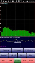
I measured the output of one of the TLS driving only the woofer in an anechoic chamber. I used a Dayton Audio iMM-6 microphone and the Audio Tool Android app.
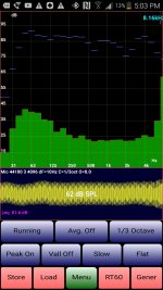
The first attached picture shows the background noise in the chamber. The 2nd attached picture shows the output of the TLS at 5' from the front of the woofer on axis. For this picture- ignore the green bars- just look at the blue line segments. I plan on initially crossing the woofer over at ~2kHz when I use a dome tweeter in a 2-way. Later, when I get my ESL's done I will replace the tweeter and crossover at a lower frequency. Note that there are dips in the frequency response at ~600Hz and 2kHz.
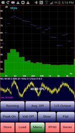
The 3rd attached picture show output of the TLS from the rear opening. Again, just look at the blue line segments. I expected to see the output dropping off faster and at a lower frequency.
Any comments would be appreciated. Any suggestions on how I can smooth out the frequency response?
Hi all-
I measured the output of one of the TLS driving only the woofer in an anechoic chamber. I used a Dayton Audio iMM-6 microphone and the Audio Tool Android app.
The first attached picture shows the background noise in the chamber. The 2nd attached picture shows the output of the TLS at 5' from the front of the woofer on axis. For this picture- ignore the green bars- just look at the blue line segments. I plan on initially crossing the woofer over at ~2kHz when I use a dome tweeter in a 2-way. Later, when I get my ESL's done I will replace the tweeter and crossover at a lower frequency. Note that there are dips in the frequency response at ~600Hz and 2kHz.
The 3rd attached picture show output of the TLS from the rear opening. Again, just look at the blue line segments. I expected to see the output dropping off faster and at a lower frequency.
Any comments would be appreciated. Any suggestions on how I can smooth out the frequency response?
Attachments
- Status
- This old topic is closed. If you want to reopen this topic, contact a moderator using the "Report Post" button.
- Home
- Loudspeakers
- Multi-Way
- Stuffing a transmission line speaker- unexpected results