The Dovedale 3 would appear to have a 3 way 2nd order reverse polarity crossover.
The basic schematic of this type of crossover may be found on the net. The specific
capacitor and inductor values relating to the Dovedale 3 crossover (450.36) are as follows:
High pass filter (to tweeter): Series capacitor 4.7uF & parallel inductor 0.5mH.
Low pass filter (to bass driver): Series inductor 4.0mH & parallel capacitor 32uF.
Band pass filter (to midrange driver): This comprises of two stages, a high pass filter (25uF & 1.0mH) followed by a low pass filter (1.25mH & 4.0uF).
Note that both the tweeter and midrange driver are connected in reverse polarity compared to the bass driver.
Hello Galu,
I know I'm getting in a little late here but only just started looking for items relating to the Dovedale (version III). I have a pair with no crossovers.
Working out the circuit from your description is easy enough but I have two questions.
1. Why are the tweeter and midrange drivers connected in reverse polarity?
2. The Dovedales I got have high and mid range level selection switches on the rear of the cabinet. Were these just switching resistors in series with the drivers?
Cheers,
Andre
Hi Andre! It's well past my bedtime here so I'll give a quick answer.
1. To keep the drivers in phase acoustically. (Crossovers can introduce 180 degree phase differences which can be compensated for by reversing the mid and treble driver leads.)
2. I think it may be as simple as that, but would require a diagram of the switching arrangements to be sure. This I do not have!
P.S. You can run the speakers without the switched resistors using the crossovers I described.
Last edited:
Thanks for the info.
Looks like I'm not the only one chasing this.
I've attached a copy of my hand drawn circuit which includes what I assume you were spelling out with the inclusion of the switching.
Hope I've got this right.
Cheers,
Andre
Looks like I'm not the only one chasing this.
I've attached a copy of my hand drawn circuit which includes what I assume you were spelling out with the inclusion of the switching.
Hope I've got this right.
Cheers,
Andre
Attachments
That's a great translation of my word description into a circuit diagram Andre.I've attached a copy of my hand drawn circuit which includes what I assume you were spelling out
And you've added in the switchable resistors to which I did not refer in my original reply. Well done - I've saved your schematic for posterity!
It's actually not long since I sold an original pair of Dovedale 3 crossover boards on ebay - resistors, switches an' all.
")
Stop Press!
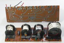
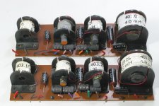
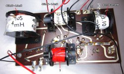
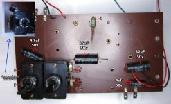
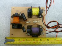
I've found the photos of the Dovedale 3 crossovers I sold on ebay.
The resistor values are visible on the attached photos and you may be able to work out which resistor goes where!
In the 'Increase' position of the switches there will be no resistor in circuit. 'Flat' must be the smaller resistor and 'Decrease' the larger resistor.
Attachments
Hi Galu,
Thanks for the complement. I hope the other member, "OV54ZXH" sees it and makes some use of it as well.
As for the photos, they are great. I can trace the track to the components and confirm that what I've drawn is hopefully correct.
Thanks again, it is really appreciated.
Cheers,
Andre.
P.S. I am a Wharfedale collector and have Airedales, Rosedales, Meltons, Dentons, Lintons, Column 8's, etc. along with a heap of drivers. However, I had a pair of Dovedales a while back and sold them so am now rebuilding this pair. I discovered that these were the rockers in the Wharfedale family. They are all super efficient so they can be run from relatively low power amplifiers and still go loud!
Glad to be of assistance Andre - and thanks for the interesting background information.
I'm a Wharfedale enthusiast, but not a collector as such. In my man shed, I'm running a pair of RS/12/DD full range speakers on period valve amplification for serious listening and a pair of tweaked Denton 2 on period transistor amplification for background listening. I bought the RS/12/DDs back in 1969 and they're still going strong these 50 years later!
I have original copies of Gilbert Briggs' books 'Loudspeakers' and 'More About Loudspeakers' and refer to them frequently.
I'm still working my way through the story of Gilbert Briggs and his loudspeakers written by David Briggs and titled 'A pair of Wharfedales'.
I do hope you have access to this book in Oz (ISBN 978-1-906715-14-4).
Happy collecting!
Attachments

Hold everything!
I've traced the printed circuit board and discovered that the switching is prior to the crossover components. I'll redraw the circuit and post it later. Hopefully others will also get some value from this. This has turned into a mission for me.
As for Briggs' books, I have nearly all of them and as you mention, they are essential reading for Wharfedale enthusiasts. I'm also in the process of building an open baffle system and the books have been most helpful in that regard.
As for the David Briggs book, it is impossible to get here and I've put in requests with overseas sellers but so far have had no luck.
I should have the updated circuit posted within a day or so.
Cheers,
Andre.
Looking forward to your revised circuit diagram. I've never come across one including the resistors and switches so it may prove very useful to other Dovedale 3 owners.
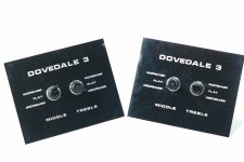
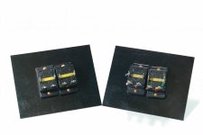
Interesting to note that there was a variant of the Dovedale 3 crossovers which had the switches mounted directly to the board instead of via flying leads. The attached photos were found on the interweb.
Interesting to note that there was a variant of the Dovedale 3 crossovers which had the switches mounted directly to the board instead of via flying leads. The attached photos were found on the interweb.
Attachments
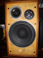
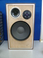
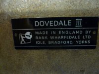
To avoid the confusion that often arises, it's worth noting that there was an earlier version of this 3-way speaker called Dovedale III as opposed to Dovedale 3.
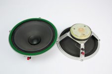
The Dovedale III has a rear mounted bass driver and access to the interior is via a removable back panel. In comparison, the Dovedale 3 has a front mounted bass driver and access is gained by removing the driver from the baffle.
The Dovedale III crossover circuit was simpler than that of the Dovedale 3 and employed no switching arrangement.
I think I may need to get out more!
Attachments
High pass filter (to tweeter): Series capacitor 4.7uF & parallel inductor 0.5mH.
Low pass filter (to bass driver): Series inductor 4.0mH & parallel capacitor 32uF.
Band pass filter (to midrange driver): This comprises of two stages, a high pass filter (25uF & 1.0mH) followed by a low pass filter (1.25mH & 4.0uF).
Correct values, but incomplete. Here the map i did when i parted a pair out.
dave
Attachments
Thanks Dave.Correct values, but incomplete. Here the map i did when i parted a pair out.
Yours is the circuit for the alternative variant of the Dovedale XO board and not the one that Andre is currently analysing. This is evident from the different resistor values and the inclusion of a 5th resistor (the 1 ohm) that is not included on the board which he and I are discussing - see earlier photos.
However, your circuit digram will be very useful to Andre as he traces the switching arrangement for our circuit board, which I believe is the later iteration.
Thanks Dave, this statement of theory is accurate.Given theory, only the midrange should be wired anti-phase given the 2nd order XO.
It's at times like this I reach for my copy of 'Loudspeakers' by Gilbert Briggs (first issued 1948).
On the subject of 2nd order crossovers he writes that "the phase shift is 180 degrees and it is worth while to ensure that the bass and middle speakers are acoustically in phase (by anti-phase connection) to avoid a dip in response around the frequency of crossover."
He goes on to say "Where the treble speaker faces upwards, reversing its phase makes little or no difference."
Paying heed to Gilbert's words of wisdom, written down in the days before computer modelling, I would recommend this course of action to Andre:
The midrange speaker should be reverse connected and it may be worth experimenting with regard to the tweeter.
I really must get out more!
Hi all,
Thanks to Galu and Planet10, I think I now have it right and will use this version to rebuild the crossovers in the Dovedales that I am restoring. I'll build them on something else as for obvious reasons the PCB is not an option. I'll post some pics when the project is complete.
By the way, how many versions of the Dovedale are there. I now know of:
1. the "3"
2. the "III"
3. some with and without switching
4. the "SP"
5. the "W2"
6. Some with a vertical bar in front of the woofer
Who knows how many more there are? Was there a "1" and a "2"?
Anyway, thanks to all for your help.
Cheers,
Andre.
Attachments
- Home
- Loudspeakers
- Multi-Way
- Wharfedale Dovedale 3