I would like to do a very slight tweek with a parallel notch filter. Does the notch filter "have to be" before the crossover? I have a 3rd BW filter that is just fine. I have a teeny touch I would like to cut out between 500 and 1khz. Can I put the cap, coil and resistor before the bass driver?... or "must" it go before the 3rd order BW filter?
Actually this is usually best after the high or low pass filters and before the driver. I encourage you to simulate your work using XSim or some other crossover simulator to get the results you are intending. ")
Not just your frequency, but making sure you don't do something wonky to the impedance curve.
Best,
Erik
Not just your frequency, but making sure you don't do something wonky to the impedance curve.
Best,
Erik
Shunt RLC and RC networks are best implemented directly across the driver terminals.I would like to do a very slight tweek with a parallel notch filter. Does the notch filter "have to be" before the crossover? I have a 3rd BW filter that is just fine. I have a teeny touch I would like to cut out between 500 and 1khz. Can I put the cap, coil and resistor before the bass driver?... or "must" it go before the 3rd order BW filter?
Dan.
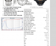
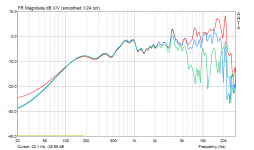
This is what I am trying to achieve. Can someone please assist me with a series notch? The online calculators give me really weird numbers. This is a parallel notch. Can someone help me with a series instead?
Attachments

Last edited:
You can have a series filter in series or parallel to the driver or a parallel filter in series or parallel to the driver. We all need to be clear on what we mean.
To drop the response you would need a parallel filter in series with the driver OR a series filter in parallel with the driver.
Which one you use and where you put it, in front of or behind the crossover filter depends on how the various filters interact with each other and the drivers impedance. There would likely not be a simple way to know this without simulating the effects.
Thanks for your time. I have been trying to work this out for myself but I am getting some really weird numbers from this calculator. Not sure where to go with this to "start" and tweek later.
mh-audio.nl - Home
mh-audio.nl - Home
A series notch filter (L, C and R) is a filter with its components wired in series where at resonance its reactive components ( L and C ) have their reactances cancel out, being 180 degrees out of phase with each other. This leaves the DC resistance of R of the filter to load the impedance of the driver. This filter is most usually wired across the driver as 'gedlee' mentions.
With the parallel notch filter the components of the filter L, C and R are wired in parallel across one another, which at resonance forms a high impedance to current flow through these reactive components. This only leaves the parallel resistance of R to largely determine any current flow through this resonant circuit to the impedance of the driver. Thus this parallel notch filter is most generally wired in series with the impedance of the driver.
As mentioned earlier it best simulated in conjunction with other filter components as such interactions can have less than predictable outcomes.
C.M
- Status
- This old topic is closed. If you want to reopen this topic, contact a moderator using the "Report Post" button.
- Home
- Loudspeakers
- Multi-Way
- Parallel notch filter question