My original Synergy corner horns need some help in the bass department. I had drivers and plywood left over from the original design so I built these sealed slot loaded woofers using the left over AE TD15Hs.
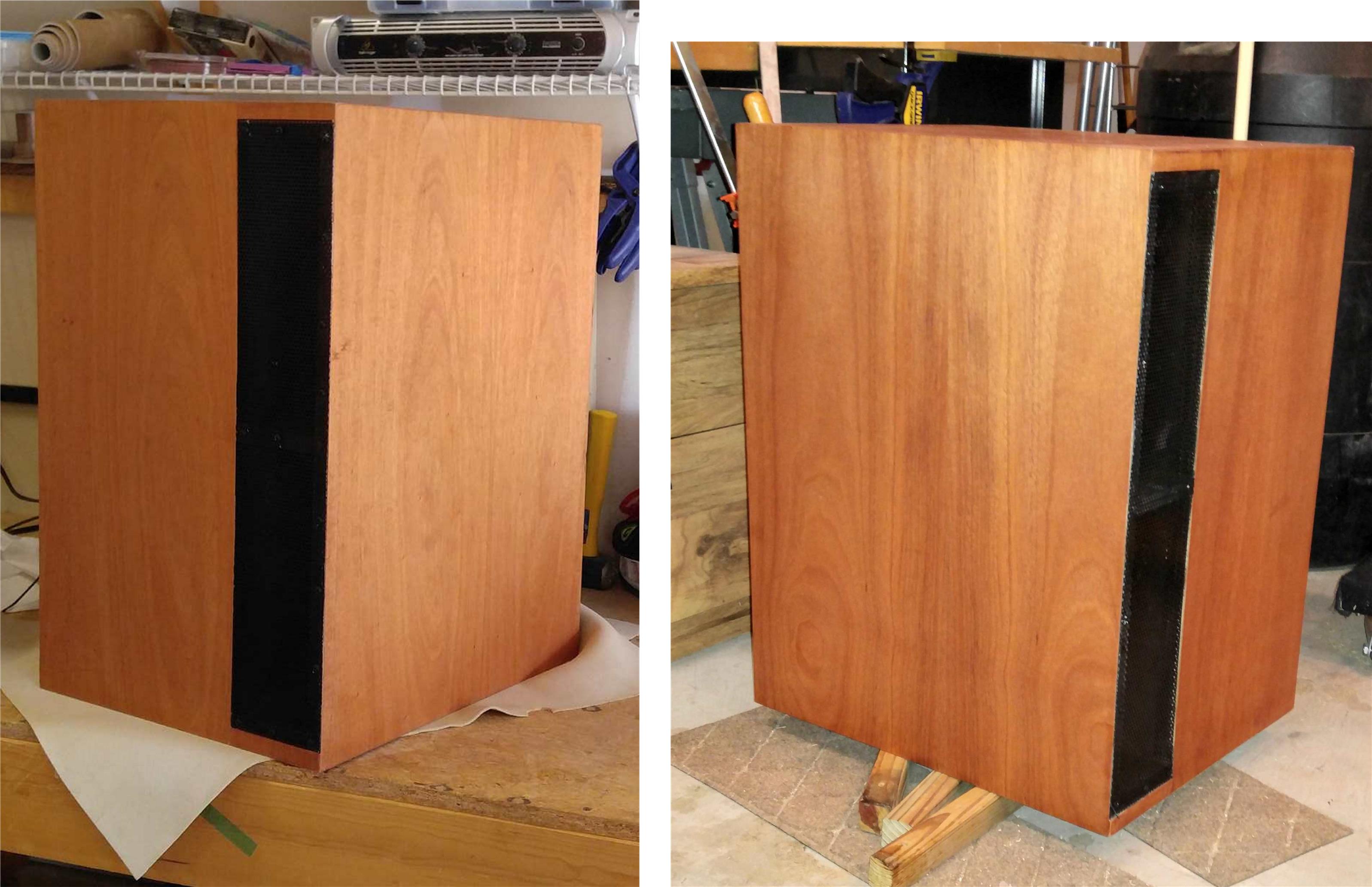
The finish to the (peel and stick) khaya veneer is a single coat of Watco Danish oil. The process calls for multiple coats but it looks so good with one I may never go further. Nevertheless, this is a 10' finish. If you look close up you will find some minor defects because I'm just minimally competent at this stuff.
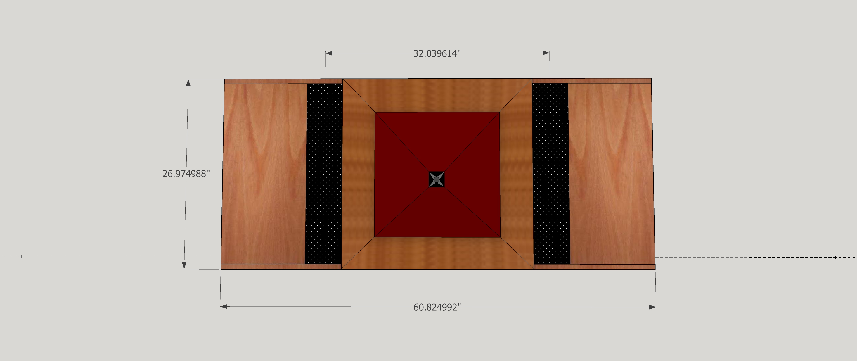
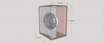
The design started with the perceived need for a center channel whose bass could augment the corner speakers plus allow me to control dialog volume independently. The concept was this:
I wanted something wide enough to support a really wide flat screen TV and that is what I got. Something that large has to be built modularly or else it will be immovable. Hence the separate woofers as close companions to the horn, showing a strong family resemblance to the corner horns.
The central Synergy is 60x60 and uses the same 1" exit BMS4550 and 4FE35 mids as my corner horns. Four of these mids are good down to 200 Hz and at 200 Hz the center to center distance is within the single point summation distance, thanks to the V-slot loading. This horn was also to have a 3D milled or printed throat with exit angle matching and round to rectangular conversion plus roundovers - an ambitious project for sure and based on how long it took me to finish the woofers (started last summer), it will be a long time before I finish it.
For the time being, I will use these woofers near field as multi-subs.
The finish to the (peel and stick) khaya veneer is a single coat of Watco Danish oil. The process calls for multiple coats but it looks so good with one I may never go further. Nevertheless, this is a 10' finish. If you look close up you will find some minor defects because I'm just minimally competent at this stuff.
The design started with the perceived need for a center channel whose bass could augment the corner speakers plus allow me to control dialog volume independently. The concept was this:
I wanted something wide enough to support a really wide flat screen TV and that is what I got. Something that large has to be built modularly or else it will be immovable. Hence the separate woofers as close companions to the horn, showing a strong family resemblance to the corner horns.
The central Synergy is 60x60 and uses the same 1" exit BMS4550 and 4FE35 mids as my corner horns. Four of these mids are good down to 200 Hz and at 200 Hz the center to center distance is within the single point summation distance, thanks to the V-slot loading. This horn was also to have a 3D milled or printed throat with exit angle matching and round to rectangular conversion plus roundovers - an ambitious project for sure and based on how long it took me to finish the woofers (started last summer), it will be a long time before I finish it.
For the time being, I will use these woofers near field as multi-subs.
Attachments

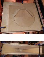
So what do these look like on the inside?
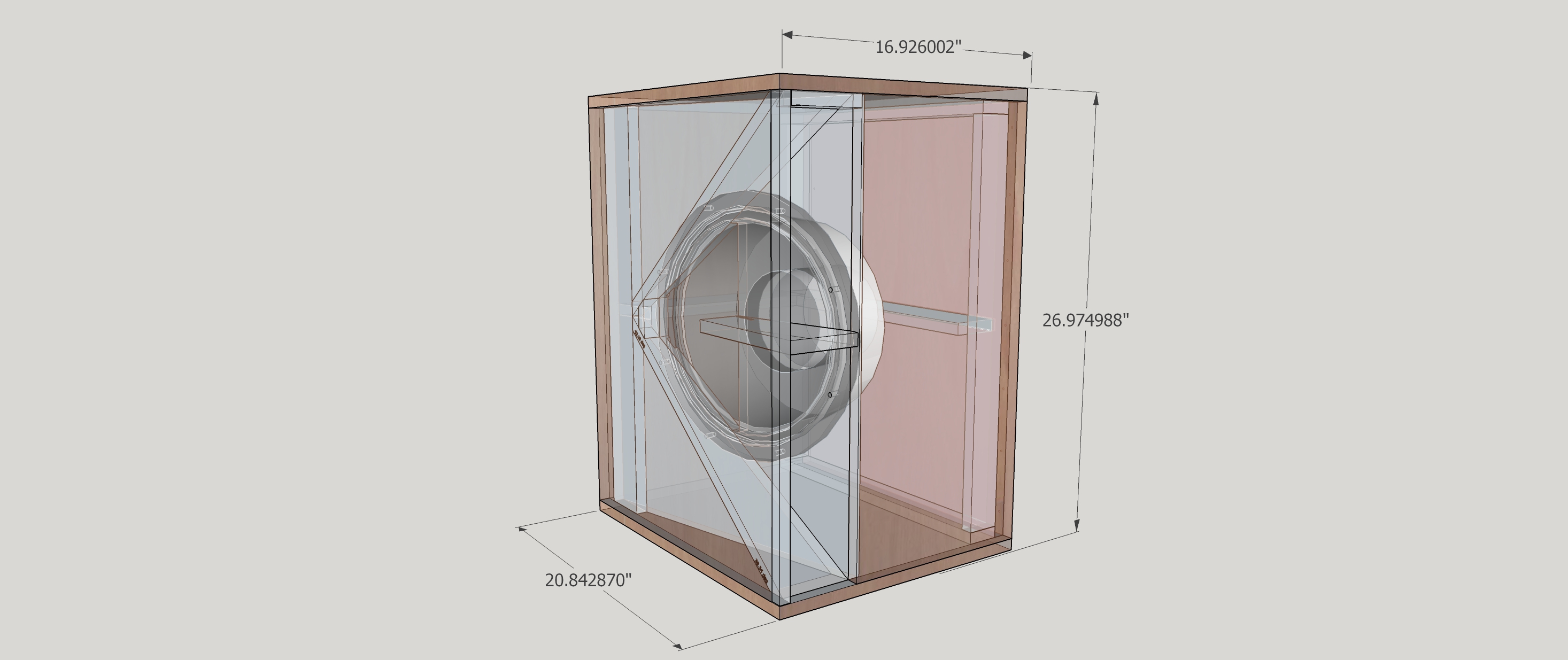
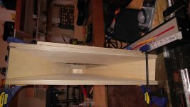
An otherwise simple box complicated by the need to cut bevels on the Vslot pieces and to implement a removable side panel.

A mounting ring provides room for the cone to move.
You see an offset 60H x ~9V conical horn with a compression ratio a little bit above 2.
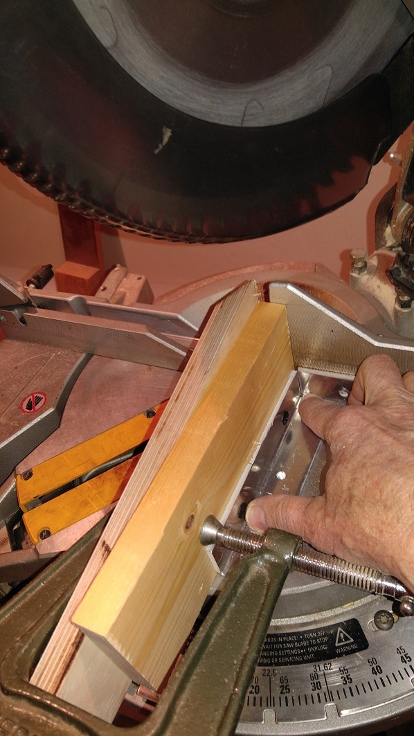
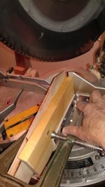
Cutting angles on some of the small pieces for the V slot made me nervous. Trying to take a picture while doing so was even worse")
An otherwise simple box complicated by the need to cut bevels on the Vslot pieces and to implement a removable side panel.
A mounting ring provides room for the cone to move.
You see an offset 60H x ~9V conical horn with a compression ratio a little bit above 2.
Cutting angles on some of the small pieces for the V slot made me nervous. Trying to take a picture while doing so was even worse
Attachments
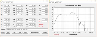
For this design, I wanted to see how high I could extend the frequency response. The HR model predicts over 600 Hz.
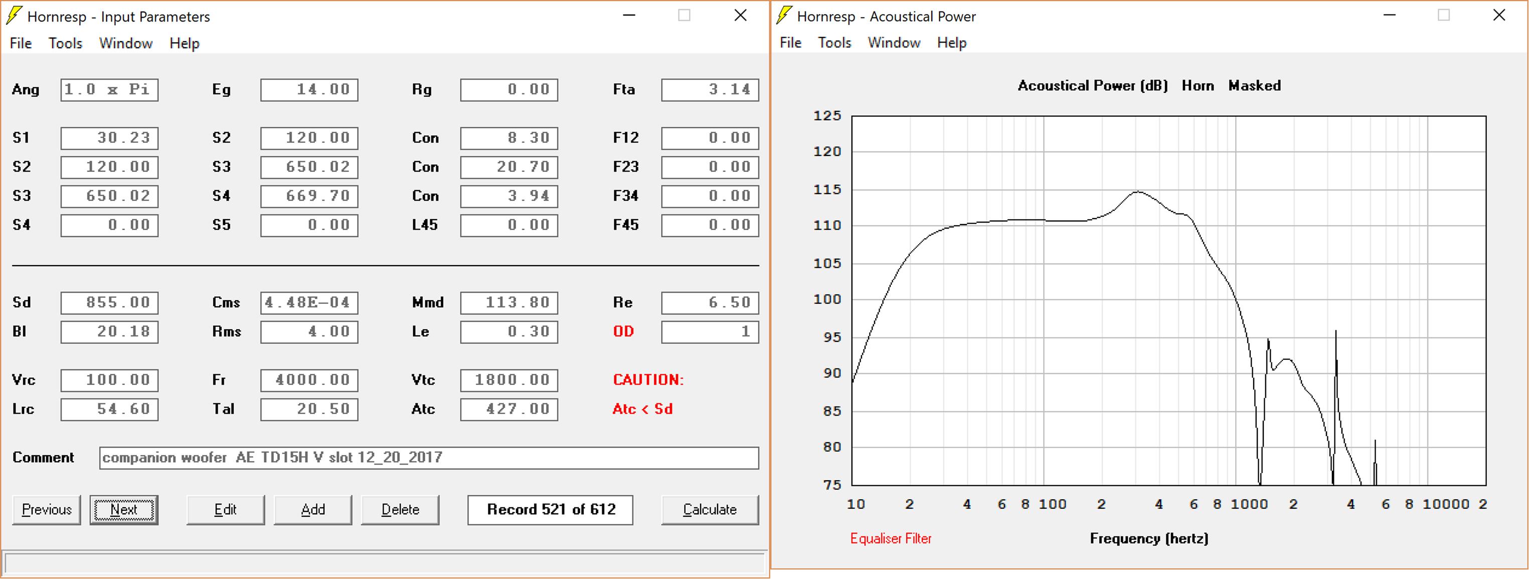
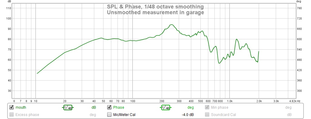
But what do measurements show?
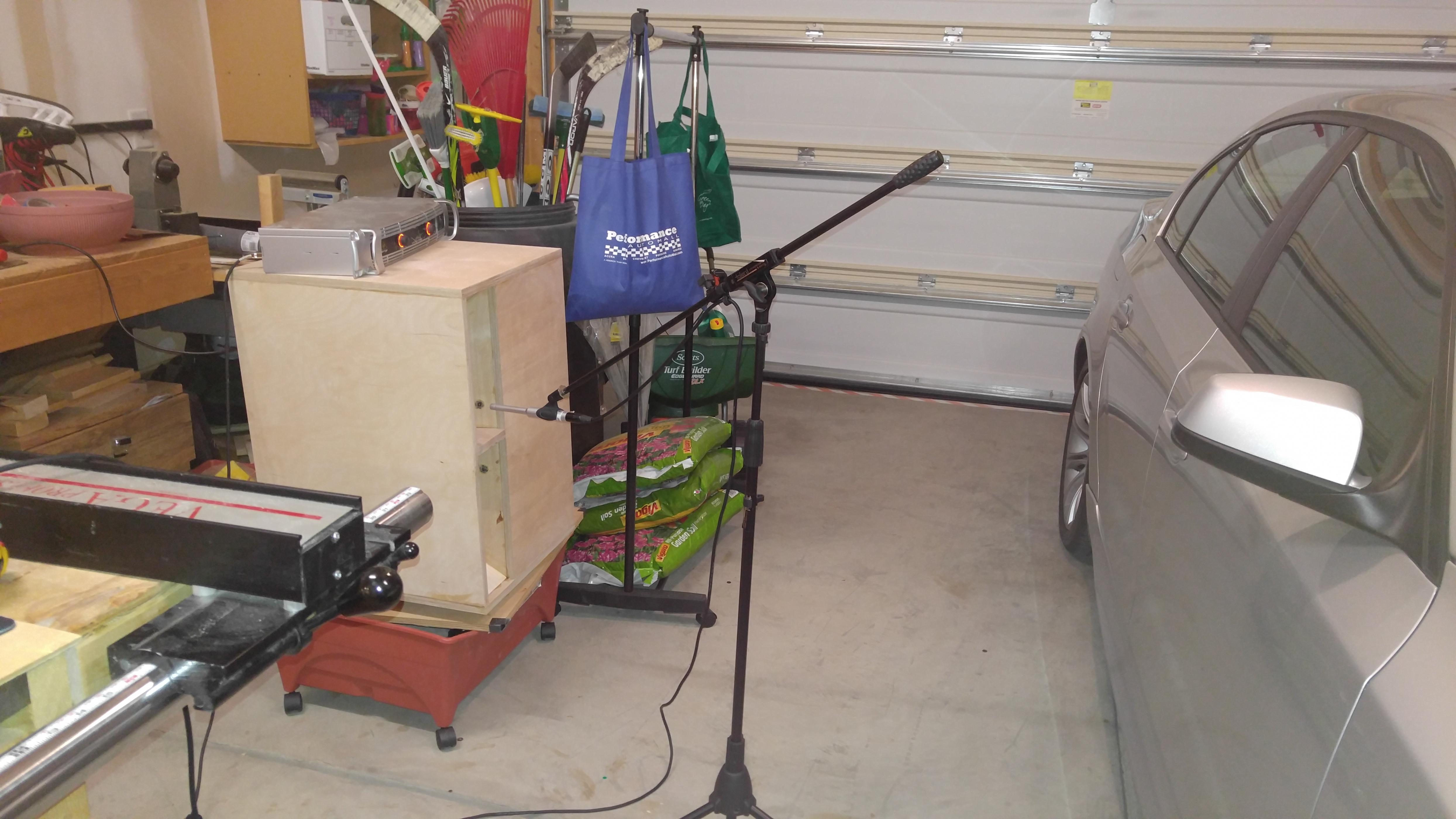
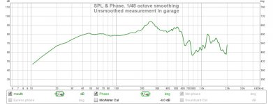
unsmoothed, quick and dirty measurement in the garage workshop
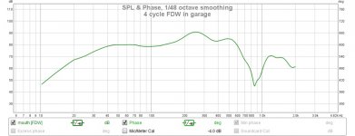
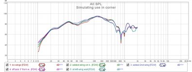
a 4 cycle FDW shows and cleaner and wider trailing edge

this final picture shows why the FDW was needed
But what do measurements show?
unsmoothed, quick and dirty measurement in the garage workshop
a 4 cycle FDW shows and cleaner and wider trailing edge
this final picture shows why the FDW was needed
Attachments

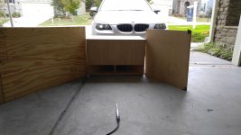
While I had the measurement gear handy I started wondering how a horizontal slot would work in a corner horn. I set up a ground plane measurement using some left over plywood to approximate corner walls.
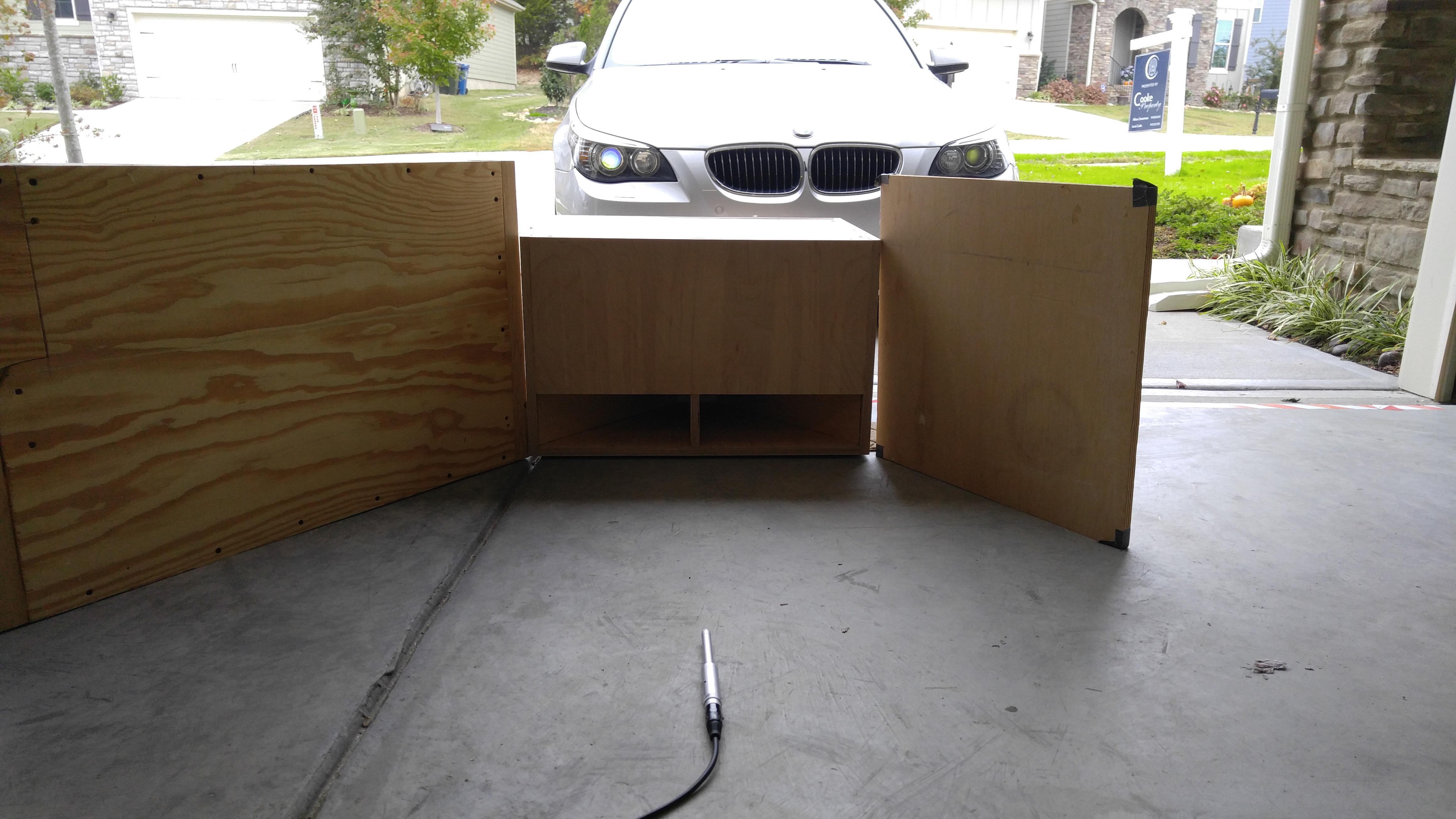
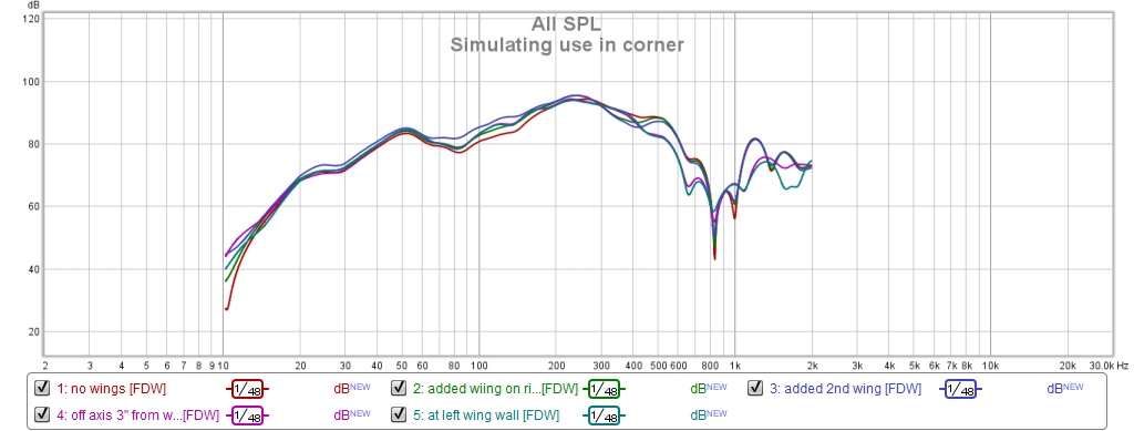
The main thing I wanted to confirm was that the response wouldn't be killed by reflections from the wing walls. Its pretty clear that it doesn't. This makes interesting possibilities for a next generation of corner horns.
I also saw further evidence that a single thickness of plywood, let alone drywall, doesn't do much to contain LF. I also saw that the HF falls off a little bit sooner when the mic is right at the wing wall.
Attachments
This is an awesome solution. You plan to use as a center channel, correct?
From a quick look at the measurements it looks like you have usable output to at least ~400hz, that should make the synergy horn easy to accomplish without being enormous.
Cheers,
Gable
Oh I think I can get it to 600 Hz with dsl of course end de ending on slope. Don't forget it's down y db at co. You have to eat to the acoustic target curve
Compound angles are no big deal once you build,the,right,sled or jig nut I have to say these were still,a PITAThank you for building this evolved slot loaded sealed box. It is great to see someone do a "what if" treatment of a concept that is flawed when done the usual rectilinear way. Of course the compound angles are no big deal for you now.
These double my displacement and add spatial diversity. I'd say my shoebox of a room,is just about adequately pressurizedI thought i heard a rumbling noise last night....
Please size your images to appropriate dimensions for the forum. 4000+ pixels wide is far too large. The forum software is not very good at resizing them. Thank you.
A small fix in the forum stylesheet will fix this:
Code:
.highslide img {
    cursor: url([url]https://files.diyaudio.com/forums/clientscript/highslide/graphics/zoomin.cur[/url]), pointer !important;
    width: 100%; /* ADD TTHIS */
}- Status
- This old topic is closed. If you want to reopen this topic, contact a moderator using the "Report Post" button.
- Home
- Loudspeakers
- Multi-Way
- Companion Woofers for my Synergy Horns