Hello all,
After build some nice 15" TH subwoofer I've been thinking about to improve my tops.
Currently I have an 10" Bass Reflex Top, not proper well designed that I want to place in a near future. (I start to go deep in loudspeakers design in this meantime)
The targets are:
I've been study tree options:
Preliminary results for the optimized Bass Reflex and Super Planar Tops are attached.
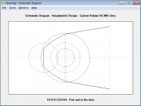
Regarding the Front Loaded Horn with vented chamber (like Altec 816), the horn flare type is PAR and considering this, what kind of expansion would better to assume for a fixed length? Your help would save me a lot of time")
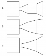
I was planning to perform a simulation matrix for the 3 flare options (A, B and C), and as a rawly simulation the best perform I found was with B type.
The horn would be tuned around 230 Hz and the port tuned to around 110Hz so the response may achieve the targets.
Matthew Morgan J dedicated theared (subwoofer and tops):
http://www.diyaudio.com/forums/subwoofers/309352-compound-loading-6th-quarterwave-super-planar-horns-pipes-concepts-builds.html
After build some nice 15" TH subwoofer I've been thinking about to improve my tops.
Currently I have an 10" Bass Reflex Top, not proper well designed that I want to place in a near future. (I start to go deep in loudspeakers design in this meantime)
The targets are:
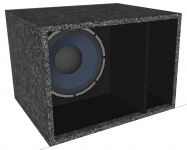
single driver 10"
frequency bandwidth: from 100Hz to 1000Hz
SPL: >100dB @2,83V@1m
Volume: < 80L
I've been study tree options:
- Bass Reflex with optimized design
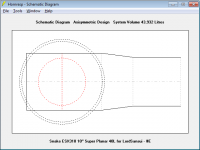
- Super Planar Tops (Thansk for Matthew Morgan J and others)
- Front Loaded Horn with vented chamber (like Altec 816)
Preliminary results for the optimized Bass Reflex and Super Planar Tops are attached.
Regarding the Front Loaded Horn with vented chamber (like Altec 816), the horn flare type is PAR and considering this, what kind of expansion would better to assume for a fixed length? Your help would save me a lot of time
I was planning to perform a simulation matrix for the 3 flare options (A, B and C), and as a rawly simulation the best perform I found was with B type.
The horn would be tuned around 230 Hz and the port tuned to around 110Hz so the response may achieve the targets.
Matthew Morgan J dedicated theared (subwoofer and tops):
http://www.diyaudio.com/forums/subwoofers/309352-compound-loading-6th-quarterwave-super-planar-horns-pipes-concepts-builds.html
Attachments
Hi weltersys
I probably should study more about matching dispersion, but my current High Frequency driver is using a horn with the coverage of 90º x 50º, is this what was missing? Larger horizontal coverage more me will be better, but looks like coverage is also a trade off for higher efficiency, so I can give up coverage for efficiency.
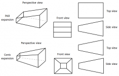
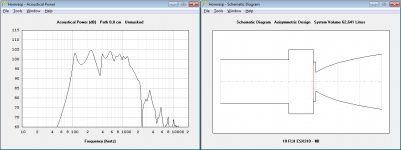
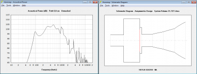
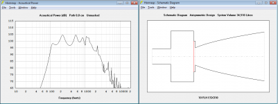
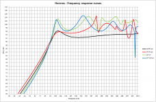
For the expansions see the attachments below:
#1 - One segment - Standard hornresp flare curve
#2 - Four segments - random angles to create like and exponential horn, assumed the same S1, length and S5
#3 - Four segments - random angles to create a different shape (like discrete standard hornresp flare), assumed the same S1, length and S5, but also with different port (higher are and length due physical design contains (a like Altec)
Except from the dip at 350Hz, the #3 was the one that presents better low end SPL and better flat response.
.
I probably should study more about matching dispersion, but my current High Frequency driver is using a horn with the coverage of 90º x 50º, is this what was missing? Larger horizontal coverage more me will be better, but looks like coverage is also a trade off for higher efficiency, so I can give up coverage for efficiency.
For the expansions see the attachments below:
#1 - One segment - Standard hornresp flare curve
#2 - Four segments - random angles to create like and exponential horn, assumed the same S1, length and S5
#3 - Four segments - random angles to create a different shape (like discrete standard hornresp flare), assumed the same S1, length and S5, but also with different port (higher are and length due physical design contains (a like Altec)
Except from the dip at 350Hz, the #3 was the one that presents better low end SPL and better flat response.
.
Attachments
A good idea is to inspect your HF horn directivity near 1000hz, it may be far off the specified angles, as the directivity near 1khz is dimension dependent.
there are few drivers that deliver a unloaded efficiency of 100dB/1m, for example the CIARE 6.38MR, but this one lacks the lower end, as heavier cones are needed to get the lower end response.
there are few drivers that deliver a unloaded efficiency of 100dB/1m, for example the CIARE 6.38MR, but this one lacks the lower end, as heavier cones are needed to get the lower end response.
I gave up. Easier to go 2 x 8". Even 2 x 6,5" can get you close.
100db/2,83v is like a magical limit on a single driver, at least in lower frequencies.
Edit:
At least if you want to have all the other goodies at the same time, like dispersion, even response, phase linearity.
100db/2,83v is like a magical limit on a single driver, at least in lower frequencies.
Edit:
At least if you want to have all the other goodies at the same time, like dispersion, even response, phase linearity.
Last edited:
but 100Hz isn't that much for a single 10" at lower end, isn't it?
an average of 98dB/2,83 would be acceptable at 4pi, with BR type I would be around 95dB/2,83, so still a good target.
The upper limit could theoreticaly be crossed at 1300Hz without beam problem.
Wave length not being lower than the drivers diameter: 344 m/s / 0,262m = 1313 Hz
Probably I would not be able to measure the horn directivity for a while so i will need to assume that maybe the system will still not have the best performance.
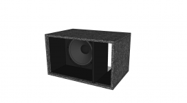
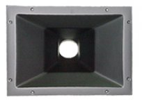
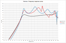
Attachement #1 indicates the CD Horn I'm currently using. It's made of fiber glass.
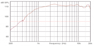
Attachement #2 indicates the CD frequency response got from the drivers data sheet (Snake Ti 2" SD375) measured with slitly different Horn, but not much different.
an average of 98dB/2,83 would be acceptable at 4pi, with BR type I would be around 95dB/2,83, so still a good target.
The upper limit could theoreticaly be crossed at 1300Hz without beam problem.
Wave length not being lower than the drivers diameter: 344 m/s / 0,262m = 1313 Hz
Probably I would not be able to measure the horn directivity for a while so i will need to assume that maybe the system will still not have the best performance.
Attachement #1 indicates the CD Horn I'm currently using. It's made of fiber glass.
Attachement #2 indicates the CD frequency response got from the drivers data sheet (Snake Ti 2" SD375) measured with slitly different Horn, but not much different.
Attachments
Matching dispersion in the 1000 Hz range is important, vocals will sound quite different on and off axis if the mid horn has a more narrow upper dispersion range than the 90º HF horn.Hi weltersys
I probably should study more about matching dispersion, but my current High Frequency driver is using a horn with the coverage of 90º x 50º, is this what was missing? Larger horizontal coverage more me will be better, but looks like coverage is also a trade off for higher efficiency, so I can give up coverage for efficiency.
I wouldn't trade uniform coverage for loudness, but it's not my circus
.weltersys,
Do you know what is the dispersion for the original Altec 816?
Maybe using different horn flare the dispersion would be OK mainly with the last segment having higher angle to reduce the bean effect as used in synergy horns.
From what I undertood, the TOP should just have more or at least equal dispersion them HF Horn but never less.
The little exponential horn on the 816 was designed to be around 90 degrees horizontal in the 500-800 Hz range.Do you know what is the dispersion for the original Altec 816?
Art
maybe it will work, once hornresp can't simulate directivity for a while I may take the risk or find another way to simulate directivity.
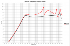
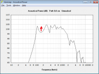
Today I made some additional simulations tuning horn flare and chambers. Below the best result I got for a while.
Is there a way to improve the first dip (like smile)?
At BR i fixed that dip just reducing the Vb, at FLH I tried to increase compression ratio but didn't work
Today I made some additional simulations tuning horn flare and chambers. Below the best result I got for a while.
Is there a way to improve the first dip (like smile)?
At BR i fixed that dip just reducing the Vb, at FLH I tried to increase compression ratio but didn't work
Attachments
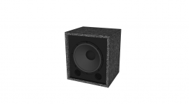
the FLH study end up with the cab volume about 101,1 L and a lot of lost spaces, the driver I have don't like big rear chamber and the port tuning require too large area due to the correlated length (horn constrain). 
An option would be to make the PORT END inside the horn so the area and the length could be reduced a lot but maybe hornresp haven't a tool to simulate it, or does it have?
For awhile, remains two options: BR and Super Planar Top
and a lot of lost spaces, the driver I have don't like big rear chamber and the port tuning require too large area due to the correlated length (horn constrain). An option would be to make the PORT END inside the horn so the area and the length could be reduced a lot but maybe hornresp haven't a tool to simulate it, or does it have?
For awhile, remains two options: BR and Super Planar Top
Attachments
An option would be to make the PORT END inside the horn so the area and the length could be reduced a lot but maybe hornresp haven't a tool to simulate it, or does it have?
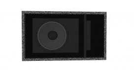
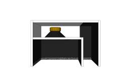
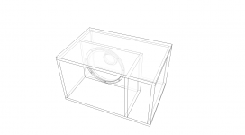
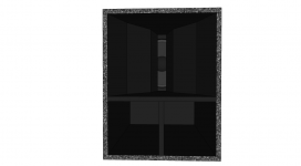
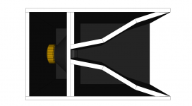
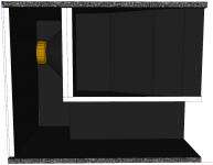
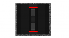
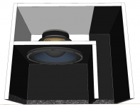
To make my question more visual, below there are two alternatives port options.
Once the port tune enhance the lower frequencies, and the wave length of those frequencies will be longer than the Horn length, will the port end inside the horn make any difference?
Horn length = 0,4 m (40cm)
Port tune frequency = 110Hz
Wave length of port tuned frequency = 3,12 m (312cm)
Quarter part of the port tuned wave length = 0,78 m (78cm)
Attachments
An option would be to make the PORT END inside the horn so the area and the length could be reduced a lot but maybe hornresp haven't a tool to simulate it, or does it have?
See the "Horn-Loaded Vented-Box Enclosure With Port Exit Located Inside Horn Mouth" entry in the Loudspeaker Models section of the Hornresp Help file.
Thank you David.
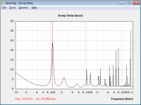
Do you know why the Group Delay at tuned port frequency became much higher using tapper horn to model it compared to what I used to find from a Bass Reflex model? (Probably is due to some effect related to the horn once the port end is inside it).
The FLH shows the a big group delay as the TH, but I was thinking that the delay increased due to port volume being much higher compared to the BR, I mean, once the port length increased a lot at FLH, to compensate I increased port area to keep the same port tune frequency but it made the port volume a lot higher.
Except from the group delay, the SPL result looks better compared to the previous options while the supper planar top is the simplest build so far.
Do you know why the Group Delay at tuned port frequency became much higher using tapper horn to model it compared to what I used to find from a Bass Reflex model? (Probably is due to some effect related to the horn once the port end is inside it).
The FLH shows the a big group delay as the TH, but I was thinking that the delay increased due to port volume being much higher compared to the BR, I mean, once the port length increased a lot at FLH, to compensate I increased port area to keep the same port tune frequency but it made the port volume a lot higher.
TH = 24,2 ms @ 110 Hz
FLH = 20,6 ms @ 110 Hz
SP = 11,2 ms @ 110 Hz
BR = 10,5 ms @ 110 Hz
Except from the group delay, the SPL result looks better compared to the previous options while the supper planar top is the simplest build so far.
Attachments
Do you know why the Group Delay at tuned port frequency became much higher using tapper horn to model it compared to what I used to find from a Bass Reflex model?.
The exact answer will be buried somewhere in the simulation model calculations, but I am not going to go looking for it
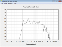
. Someone with more practical experience in these matters than me, may know why specifically. Intuitively though, I would have expected the group delay performance to be inferior, given the rapid phase changes inherent in a tapped horn design.Due to build complexity and size being more favorable to Super Planar I made additional improvements where the result can be found attached.
it's +3dB output compared to BR from the lower limit till around 50% of the bandwidth.
The cab directivity is unknown but it will worth the risk.
The total volume is 57,1L and it's easier and chipper to build compared to BR once it doesn't need filling or port.
Let's see what can I do in my next vocation
Attachments
I'm planning to cross over around 1000Hz, this frequency wouldn't be a problem for the 10" driver that is able to reproduce frequencies till 1300Hz without big beam problem, so maybe the phase plug woundn't help too much, or am I missing somethink?
Phase plug is necessary when we want to extend upper frequencies so it helps to reduce the cancellations close to the driver, right?
Phase plug is necessary when we want to extend upper frequencies so it helps to reduce the cancellations close to the driver, right?
Phase plug is necessary when we want to extend upper frequencies so it helps to reduce the cancellations close to the driver, right?
Correct. it helps to reduce cancellations of the higher frequencies. You can experiment with it by partly blocking the sides of the cone. so making the mouth a vertical slot.
Or (partly) blocking the center of the cone (dustcap) this is the simplest type of a plug you can think of. You can also add some triangle type reflectors on the four sides of the woofer corners, it will probably help control standing waves in mid/high frequency range. You can test a lot of options on this design.
Did you try other drivers to see if the dips change?
Last edited:
Nop,
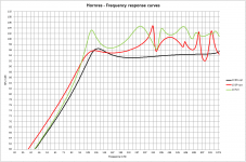
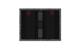
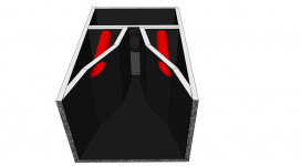
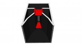
I just performed a lot of simulations, like virtual DoE to reduce the dip and one good contributor I found was to have different expansion area between S3 and S4. The images I posted give you some idea and the image below can clear better.
I'm crossing my finger to David implement an improvement to hornresp to allow us to simulate different front resonator shape, it may help us to improve the the frequency response.
The improvements you suggest need to be done by trial and error and they can't be simulated.
I think the dip can't be eliminated because there will always be a cancellation between front waves and back waves. I can live the dip if I find a way to get flatter response from 100Hz to 300Hz where the punchy is more evident and where the loudness effect is also more perceived.
I'm opened to check any proposal
Attachments
- Status
- This old topic is closed. If you want to reopen this topic, contact a moderator using the "Report Post" button.
- Home
- Loudspeakers
- Multi-Way
- 10" top design - Open discussion