Got a horn project in the planning stage that I hope you wiser folks can help advise/guide me on. First some background.
Like many DIY audio folks, I am a tinkerer and sometimes woodworker who is always hoping for the best sound at the lowest price. Years ago, I became fascinated with the high efficiency and low distortion of horn loaded speakers, and dreamed one day of building a pair of Speakerlab Ks (their DIY version of a Klipschorn). Then life supervened-I got married, left the bachelor lifestyle, and raised kids. Speakerlab went out of business, and my wife got me a Bose Acoustimass 5 set (which has grown to 7), which became the default (although somewhat anemic) sound system for our TV/family room.
A few years back, we decided to have some nice custom cabinets made for this room (which is about 16 feet square), and this included a cabinet for the TV, which we always had kept in one corner. So this particular tall TV cabinet (shown below) cuts across that corner, leaving a triangular shaped space behind. When I realized this during our planning, I saw an opportunity to build a horn loaded subwoofer to fit in that space, which I did. (It’s an exponential horn with a triangular cross-section, which runs up the wall in the corner space behind the cabinet to about 18 inches from the ceiling, where it makes a 90° turn, using the ceiling, corner walls and cabinet top to complete an “invisible” ~8ft wide mouth).
I’ll describe it more fully here some other time; It was not entirely successful (it has some resonances), but it was fun, and to my ear at least can produce a fairly clean sine wave, without doubling, down to around 35 Hz, which has added some tactile rumble to DVD soundtracks. Most importantly, being behind the cabinet, it was unseen and thus spouse-friendly.
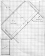
Now that I am nearing retirement, I have time and inspiration to finally try to complete my DIY spouse-friendly (single) Klipschorn-of-sorts. I’ve procured a single K52/K-700 midrange and a K77 tweeter off of eBay for a reasonable price. The frequency range left to fill (for this single speaker, which will be the center speaker in my AV 7.1, as well as for music - the multiple “full-range” Bose satellites will have to provide stereo/surround imaging for now ) is from 150 Hz (where my older Marantz AV receiver rolls off my DIY subwoofer) to around 700 - 1000 Hz, where the K-700 will take over. Since TV’s have now become very thin, I now have a space to hide this all in, which looks like this from the top:
And here's the cabinet (and TV) from the front:
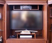
Everything below the TV (including its stand) can go away. If I keep the AV receiver over the TV, I can skootch the TV up (as shown) to leave a space below it around 50” wide and maybe 12” tall to fit horn mouths. (I could also maybe move the AV receiver and its shelf to some cabinets below, increasing the mouth space height another 6“ or so, to 18“ total height ). (next post)
Like many DIY audio folks, I am a tinkerer and sometimes woodworker who is always hoping for the best sound at the lowest price. Years ago, I became fascinated with the high efficiency and low distortion of horn loaded speakers, and dreamed one day of building a pair of Speakerlab Ks (their DIY version of a Klipschorn). Then life supervened-I got married, left the bachelor lifestyle, and raised kids. Speakerlab went out of business, and my wife got me a Bose Acoustimass 5 set (which has grown to 7), which became the default (although somewhat anemic) sound system for our TV/family room.
A few years back, we decided to have some nice custom cabinets made for this room (which is about 16 feet square), and this included a cabinet for the TV, which we always had kept in one corner. So this particular tall TV cabinet (shown below) cuts across that corner, leaving a triangular shaped space behind. When I realized this during our planning, I saw an opportunity to build a horn loaded subwoofer to fit in that space, which I did. (It’s an exponential horn with a triangular cross-section, which runs up the wall in the corner space behind the cabinet to about 18 inches from the ceiling, where it makes a 90° turn, using the ceiling, corner walls and cabinet top to complete an “invisible” ~8ft wide mouth).
I’ll describe it more fully here some other time; It was not entirely successful (it has some resonances), but it was fun, and to my ear at least can produce a fairly clean sine wave, without doubling, down to around 35 Hz, which has added some tactile rumble to DVD soundtracks. Most importantly, being behind the cabinet, it was unseen and thus spouse-friendly.
Now that I am nearing retirement, I have time and inspiration to finally try to complete my DIY spouse-friendly (single) Klipschorn-of-sorts. I’ve procured a single K52/K-700 midrange and a K77 tweeter off of eBay for a reasonable price. The frequency range left to fill (for this single speaker, which will be the center speaker in my AV 7.1, as well as for music - the multiple “full-range” Bose satellites will have to provide stereo/surround imaging for now

And here's the cabinet (and TV) from the front:

Everything below the TV (including its stand) can go away. If I keep the AV receiver over the TV, I can skootch the TV up (as shown) to leave a space below it around 50” wide and maybe 12” tall to fit horn mouths. (I could also maybe move the AV receiver and its shelf to some cabinets below, increasing the mouth space height another 6“ or so, to 18“ total height ). (next post)
So here’s the plan:
I had hoped this extra space might be enough space for a straight midbass horn, but HornResp and some research says not so - the depth of the cabinet (24") is just not long enough for a 150 Hz straight horn. It is, however, just enough space to put in a longer curved one *behind* the TV like this (as viewed from the side):
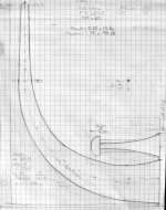
After playing with HornResp for too long, and modeling out different drivers, this is what I get with a 118 cm tractrix horn (taken from HornResp, with some additions, but the SPL curve is unchanged):
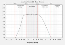
Looks great to me, but I learned with the subwoofer project there can be a *big* distance between theory and performance. I also tried similarly sized exponential, hypex, and LeCleac’h horns, but they didn’t model quite as well. Now, that predicted SPL above is in 1pi space, and it’s really kind of a ~1.5 pi setting: it’s in a corner, but the mouth would be a couple of feet from the nearest corner/cabinet walls. But the 2 pi space SPL looks reasonably good as well:
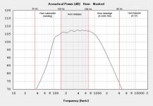
(BTW, part of this four-way possible design comes from this page, which suggests horns should only try to cover a 1x to 10x frequency range, and also I thought it could be interesting to try to cover the majority of fundamental frequencies of the human voice with a single horn, since this will do double duty as a center speaker in my 7.1 setup. Also, I read here from Mr./Dr./Professor LeCleac’h that it’s best if the lower Xover for a horn comes at twice its Fs, which in this design is 84 Hz, so I’m pretty close there.)
The driver that modeled out best of the dozen or so I considered was actually a B+C 6PEV13, a 6” midbass driver with a good Bl of 8.2, a Fs of 126Hz, and a Qes of 0.39, giving a EBP (Fs/Qes) of 323, which from my reading seems like it could be reasonably suited to horn loading. The predicted SPLs shown above use a throat area of 40 sq cm (around a 3.5:1 compression ratio) and a mouth of 1625 sq cm (with a mouth circumference very close to 1 wavelength at 150 Hz)
So my first question is, what do you think of the plan in general? And remember I’m a newbie, so please be kind. ; )
(specific design ideas next post)
I had hoped this extra space might be enough space for a straight midbass horn, but HornResp and some research says not so - the depth of the cabinet (24") is just not long enough for a 150 Hz straight horn. It is, however, just enough space to put in a longer curved one *behind* the TV like this (as viewed from the side):

After playing with HornResp for too long, and modeling out different drivers, this is what I get with a 118 cm tractrix horn (taken from HornResp, with some additions, but the SPL curve is unchanged):

Looks great to me, but I learned with the subwoofer project there can be a *big* distance between theory and performance. I also tried similarly sized exponential, hypex, and LeCleac’h horns, but they didn’t model quite as well. Now, that predicted SPL above is in 1pi space, and it’s really kind of a ~1.5 pi setting: it’s in a corner, but the mouth would be a couple of feet from the nearest corner/cabinet walls. But the 2 pi space SPL looks reasonably good as well:

(BTW, part of this four-way possible design comes from this page, which suggests horns should only try to cover a 1x to 10x frequency range, and also I thought it could be interesting to try to cover the majority of fundamental frequencies of the human voice with a single horn, since this will do double duty as a center speaker in my 7.1 setup. Also, I read here from Mr./Dr./Professor LeCleac’h that it’s best if the lower Xover for a horn comes at twice its Fs, which in this design is 84 Hz, so I’m pretty close there.)
The driver that modeled out best of the dozen or so I considered was actually a B+C 6PEV13, a 6” midbass driver with a good Bl of 8.2, a Fs of 126Hz, and a Qes of 0.39, giving a EBP (Fs/Qes) of 323, which from my reading seems like it could be reasonably suited to horn loading. The predicted SPLs shown above use a throat area of 40 sq cm (around a 3.5:1 compression ratio) and a mouth of 1625 sq cm (with a mouth circumference very close to 1 wavelength at 150 Hz)
So my first question is, what do you think of the plan in general? And remember I’m a newbie, so please be kind. ; )
(specific design ideas next post)
Question 2: the space I have to fit the mouth into is a pretty elongated rectangle. And where am I going to put the K-700 and the K77?
Some design ideas:
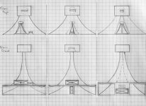
A) Pure (skinny) midbass horn mouth below, then K-700 and K77 (either landscape or portrait orientation) above (the K-700 *barely* fitting depth-wise, and leaving space on either side for our small Blu-Ray player and other TV boxes below the TV).
B) Midbass horn below, partially/minimally bifurcated near the end, just enough to fit in K77 tweeter (portrait orientation), with K-700 above
C) Larger bifurcation of midbass horn (with bifurcation maybe extending back to throat) to fit in K-700 *and* K77 (landscape orientation).
Option A results in a simpler and more “pure” horn, *but* a rather elongated mouth, with a height to width ratio of ~5.5:1. Option C produces a two mouthed horn, from a single driver (kind of like a multicell horn where n=2). Each half has a closer-to-square mouth, but I have no idea of how to model this in HornResp or what the overall effect of the bifurcation would be.
I should also mention that beaming shouldn’t be a huge problem, since the wife and I will usually be sitting more-or-less directly in front of the proposed speaker (about 9 feet away).
Any advice from the gurus at diyaudio would be greatly welcomed!
Some design ideas:

A) Pure (skinny) midbass horn mouth below, then K-700 and K77 (either landscape or portrait orientation) above (the K-700 *barely* fitting depth-wise, and leaving space on either side for our small Blu-Ray player and other TV boxes below the TV).
B) Midbass horn below, partially/minimally bifurcated near the end, just enough to fit in K77 tweeter (portrait orientation), with K-700 above
C) Larger bifurcation of midbass horn (with bifurcation maybe extending back to throat) to fit in K-700 *and* K77 (landscape orientation).
Option A results in a simpler and more “pure” horn, *but* a rather elongated mouth, with a height to width ratio of ~5.5:1. Option C produces a two mouthed horn, from a single driver (kind of like a multicell horn where n=2). Each half has a closer-to-square mouth, but I have no idea of how to model this in HornResp or what the overall effect of the bifurcation would be.
I should also mention that beaming shouldn’t be a huge problem, since the wife and I will usually be sitting more-or-less directly in front of the proposed speaker (about 9 feet away).
Any advice from the gurus at diyaudio would be greatly welcomed!
These are more of a concern when you use horns with solid loading qualities and less as you move toward conical.suggests horns should only try to cover a 1x to 10x frequency range
...
that it’s best if the lower Xover for a horn comes at twice its Fs,
Pdq2,
You should read up on the articles Dr. Bruce Edgar published in Speaker builder magazine in the 1980's on / diy horns / theory etc. -- just to further your knowledge.
A tip on building horns. Getting a nice curved, precise bend in wood is a PIA to say the least. A method I used is to make a set of ribs made from 3/4" plywood matching the curve you need --say 4 or 5 or enough to cover the size needed. You would mount these ribs spaced out on another piece of flat plywood used as the base. This will give you a form in which you can use bendable plywood to form one part of your horn pattern. You can use multiple layers---use furniture commercial grade epoxy---NOT any type of yellow wood glue as it will "creep" over time and humidity changes. Glue one layer at a time and use several clamps overnight till cured and repeat the process. You have a rigid, permanent shape in which you could paint or veneer.
I made a pair of front loaded horns (using above procedure) using a pair (in parallel) of Altec 515b's 16 ohm drivers with 10" throats and hypex profile. This horn is approx 48" deep 44" high and 32" wide. In my room it measures flat from 58hz to 450 hz. at about 107db to match the 2" field coil midrange horn at 400 hz. I used oak veneer inside and oak wainscot on the outside. I suck with computers / programs so Dr. Bruce figured out the dimensions for me. I realize I should have taken pictures while working on my project to help others but didn't and regret it now. Hope this info helped and good luck with your project. There is NO substitute for a proper mid bass horn !!!
Hottattoo,
Thanks for the advice. I’ve read The Edgar Midrange Horn, and a number of other horn theory articles in trying to edumacate myself for this project.
You mentioned something I’d considered- veneering the visible, inside part of the mouth (although I ‘d use pecan to match the cabinet). I take it this caused no problems with vibrating veneer, etc? Having not yet done veneering, did you use contact cement, or something else?
Finally, thanks for your last line in your post- I’ve heard this from others, and that’s a big part of my inspiration in this project.
PS- wow! I didn't realize Dr. Edgar had a whole *series* of articles on horn design! From your suggestion, I looked around and came across this one which goes into much greater detail about horn design from first principles, mass rolloffs, and things like reactance annulling with rear chamber tuning.
Cool! So far, much of it reinforces what I came up with in HornResp by trial and error (perhaps not surprising, since physics is physics) but that's reassuring, and has given me a few new things to think about.
Thanks again!
Cool! So far, much of it reinforces what I came up with in HornResp by trial and error (perhaps not surprising, since physics is physics) but that's reassuring, and has given me a few new things to think about.
Thanks again!
1. This might not matter
2. You may already know
The K77 tweeter (EV-T-35) is designed to be placed vertically not horizontally. I don't know why Klipsch places it horizontally....perhaps it keeps wood costs down.... I DO feel that it looks nicer but as I've always said, I don't hear with my eyes.
Anyway, you might know this already. If not, you can easily find a PDF on the EV that gets into the coverage angles. (and again, in the practical world, it might not matter how it's positioned, I don't pretend to know)
1. This might not matter
2. You may already know
The K77 tweeter (EV-T-35) is designed to be placed vertically not horizontally.
Thank you. I had read that once (right here, I think). But it’s nice to get that confirmed.
I understand that’s because horizontal dispersion (somewhat counterintuitively) is wider when you mount the tweeter in the way where it’s narrower side-to-side (ie “portrait” orientation)?
Do you know, is that also true of the K700?
(Since I first posted, I’ve had additional design thoughts that involve putting both in “portrait” orientation).
One other question, regarding time alignment probs inherent in a all-horn speaker using horns of (obviously) different lengths. My AV receiver adjusts for time delay between speakers (ie center vs RF vs LF vs subwoofer etc)...or at least I think it does - I went through this setup procedure with it back when I got it where You put a microphone where you’re likely to be sitting, and it adjusts things automatically. And if you go into its menus, it tells you how far away the various speakers are from the listening spot.(!)
Now, maybe I’m being penny-wise and pound foolish in this project (or just over-the-top), but I plan to multi-amp my multi-horn speaker, and got a cheap ($65) rack mount active crossover on eBay to further this goal. My AV receiver is not going to time-align the various horn components of this speaker I’m making. But I see that a different slightly more expensive (+$20) active crossover has this capacity, up to a 2 msec delay adjustment.
Two msec translates to ~2.25 feet at the speed of sound, which isn’t quite enough to correct between a 3 foot midbass horn and the ~1 inch T77 tweeter horn (when the mouths will be lined up), but it’s close. One commenter said if the tweeter hits your ears before the midbass/mid in a transient, it makes the speaker sound “harsh”. But is 2 msec really worth the trouble of returning the cheaper active crossover for the one with the adjustable time alignment?
pdq2,
There is a debate amongst some wood workers about the proper bonding of veneers, I used the same commercial epoxy as I used to build the horns. You can use commercial grade contact cement but the longevity of the bond is not as sure although some pro wood workers say that properly done, using a vacuum bagging system works just fine. You should be fine using either bonding methods. Just follow the instructions.
The best, IMHO, tweeter out now (for high efficiency horn use) is the Fostex t500 mk2. (110db efficiency). I use a TAD ET-703 which I feel is the best as my other driver diaphragm's are beryllium but they are almost unobtanium and $$$$. I also have the Fostex t500 mk2 which is excellent. Another possibility is the RAAL Lazy Ribbon which has a transformer where you can select impedance / efficiency. A cheaper and good tweeter is the EV T350 ( ebay ) but not made anymore. Everything depends on budget / size and your end goal.
You should also check out wwwgoodsoundclub.com run by Romy the cat. Check out his "Mercondo" horn system. There is lots of excellent information about everything high end / high efficiency audio. You will be reading for days !!!!
ie. It loses control at a higher frequency.I understand that’s because horizontal dispersion (somewhat counterintuitively) is wider when you mount the tweeter in the way where it’s narrower side-to-side (ie “portrait” orientation)?
the little K700 horn is strong to cutoff with a cheap midrange driver. I'm not sure of a midbass horn to reach 700 and fit.
no baffle on these horns
http://i.imgur.com/vdMWnxF.gif
no baffle on these horns
http://i.imgur.com/vdMWnxF.gif
There is a debate amongst some wood workers about the proper bonding of veneers, I used the same commercial epoxy as I used to build the horns. You can use commercial grade contact cement but the longevity of the bond is not as sure although some pro wood workers say that properly done, using a vacuum bagging system works just fine. You should be fine using either bonding methods. Just follow the instructions.
Thanks for the advice. I'm not sure if I will want to show off the midbass horn mouth or hide it, the K700 and the T77 all behind a single screen.
The best, IMHO, tweeter out now (for high efficiency horn use) is the Fostex t500 mk2. (110db efficiency). I use a TAD ET-703 which I feel is the best as my other driver diaphragm's are beryllium but they are almost unobtanium and $$$$. I also have the Fostex t500 mk2 which is excellent.
Hoo! Over $1k per piece here. (but you can get a 10% discount if you buy 10-10,000
A cheaper and good tweeter is the EV T350 ( ebay ) but not made anymore.
Well, now you're getting closer, but I already went for the even cheaper little brother T35/K77. I may have settled for too little, but I found that either my ears or that tweeter only go up to 14-15K Hz.
You should also check out wwwgoodsoundclub.com run by Romy the cat. Check out his "Mercondo" horn system. There is lots of excellent information about everything high end / high efficiency audio. You will be reading for days !!!!
Will do. Thanks!
pdq2
Could you redo the cabinet to allow for a straight 150Hz conical mid bass horn using the B&C8PE21 to jut out from the back of the cabinet and then pretty it up. Contact John from Inlow sound inlowsound.com . He may have some ideas that work. And then go multi smaller subs below that as per Geddes.
SMathews
Yeah, I'm not sure the wife would like me taking my saber saw to her nice cabinet. And again, there is a subwoofer horn just behind the cabinet which leaves limited space.
But I am in the process of putting together my first test horn (a straight exponential horn that *would* fit in the existing cabinet). It's almost certainly too short for the bass extension I'm looking for, but I wanted to try some things out and see if the result is as expected from HornResp modelling.
I'll post photos and results in a couple of days when it's done.
The Oris horns by BD-Design use fullrange drivers to get a widerange response. They are relatively short tractrix horns. The largest model reaches to about 175Hz if I recall correctly. I would look there for inspiration. With a large enough driver, you should be able to reach down low enough in a straight tractrix horn and having no folds helps with clean sound and more upper extension. The intended crossover frequency should not be the top response of your midbass horn. I learned that the hard/disappointing way. 
If you do need to fold, Bruce Edgar showed in his bass horn articles that a 90 degree fold with a 45 degree reflector performs better than a rounded bend.
If you do need to fold, Bruce Edgar showed in his bass horn articles that a 90 degree fold with a 45 degree reflector performs better than a rounded bend.
Made my first test horn. It’s just a straight exp horn with a uni expansion (ie both tops and sides curved). I was going for kind of a baseline, with(hopefully) low coloration/distortion with which to compare subsequent designs to. It’s not long enough to go as low as I eventually want, but I did pick a design short enough to fit in the target TV cabinet, in case it pleasantly surprised me. (It didn’t, I’m afraid).
Anyway, here’s the parts, laid out per the excellent HornResp, cut out of 1/8” mdf/masonite; easy to curve:
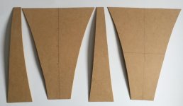
The B+C 6PEV13 and throat plate, with ~3:1 compression ratio, and 3:1 aspect ratio (same as mouth) rectangular throat.
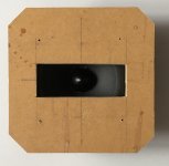
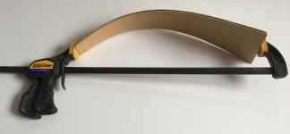
and the test horn, before and after the glue dried (just silicone caulk for now; prob use construction adhesive or something else for the next one):
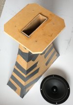
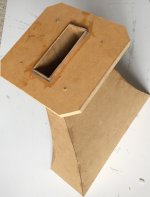
Preliminary results next post.
Anyway, here’s the parts, laid out per the excellent HornResp, cut out of 1/8” mdf/masonite; easy to curve:


The B+C 6PEV13 and throat plate, with ~3:1 compression ratio, and 3:1 aspect ratio (same as mouth) rectangular throat.

and the test horn, before and after the glue dried (just silicone caulk for now; prob use construction adhesive or something else for the next one):


Preliminary results next post.
While listening tests are obviously key, I haven't got that setup yet, and I did want to look at some objective things too in this project. The graphs below are kind of a poor-man's frequency response curve, generated from a couple of phone and iPad apps. Audio Function Generator produces sine/square/etc tones and sweeps as well as white and pink noise. I got the "Pro" version for $2, and just used white noise, through a 40W Russound amp.
Audio Spectrum Analyzer (also "Pro", $4) does FFT analysis (or "octave RTA") of sound though the built-in microphone in your device, which gave me the frequency response curves. The first graph is the octave OTA (smooth line) overlaid on the FFT (spiky yellow, with min-to-max blue areas):
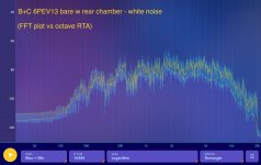
Obviously these are not pro quality products. First of all, I doubt my (iPad) microphone registers much of anything below 100 or above 15K. And the FFT is just a instantaneous screen capture - there's a fair amount of movement (as shown by the min-max range), but it seems to correlate with the octave RTA. I hoped that these might give me some objective idea of how the sound was being altered.
Just sticking with the simpler RTA plot, here's the effect of just mounting the driver on the throat plate (same audio levels, same positioning, no eq - brighter yellow line is with throat plate):

There was a greater modification than I had hoped for, frankly. The 3:1 compression may have smoothed the response slightly in some ranges (1K-2K), but the response overall is altered, and perhaps not for the better. I may try cutting test throat plates with a square hole or a round one of the same area as the rectangle to see if those cause similar effects (again, before adding the horn).
Anyway, the last set of curves is with the horn attached (again, brighter yellow line is with horn):
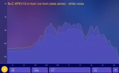
Again, not great. The horn generally seems to add maybe 5-15dB of gain, but it does so at the expense of making the frequency response even more irregular. (I think the big dip at around 3K _might_ be cancellation by the back wave, since the wavelength is around 4.5", or the distance from front to back of the driver, and my rear chamber is not very well sealed. But in any case, my target range for this driver+horn is 150-800 Hz or so).
Also, there some new dips and peaks:
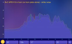
I wonder if this is reflections/resonances within the horn itself. HornResp predicts some ripple:
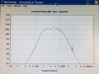
...although I'm not sure it lines up with what I've marked above.
Anyway, next I'll do some listening tests, which I don't have much hope for, and check out some different throat plates before I try a different/probably longer horn.
Audio Spectrum Analyzer (also "Pro", $4) does FFT analysis (or "octave RTA") of sound though the built-in microphone in your device, which gave me the frequency response curves. The first graph is the octave OTA (smooth line) overlaid on the FFT (spiky yellow, with min-to-max blue areas):

Obviously these are not pro quality products. First of all, I doubt my (iPad) microphone registers much of anything below 100 or above 15K. And the FFT is just a instantaneous screen capture - there's a fair amount of movement (as shown by the min-max range), but it seems to correlate with the octave RTA. I hoped that these might give me some objective idea of how the sound was being altered.
Just sticking with the simpler RTA plot, here's the effect of just mounting the driver on the throat plate (same audio levels, same positioning, no eq - brighter yellow line is with throat plate):

There was a greater modification than I had hoped for, frankly. The 3:1 compression may have smoothed the response slightly in some ranges (1K-2K), but the response overall is altered, and perhaps not for the better. I may try cutting test throat plates with a square hole or a round one of the same area as the rectangle to see if those cause similar effects (again, before adding the horn).
Anyway, the last set of curves is with the horn attached (again, brighter yellow line is with horn):

Again, not great. The horn generally seems to add maybe 5-15dB of gain, but it does so at the expense of making the frequency response even more irregular. (I think the big dip at around 3K _might_ be cancellation by the back wave, since the wavelength is around 4.5", or the distance from front to back of the driver, and my rear chamber is not very well sealed. But in any case, my target range for this driver+horn is 150-800 Hz or so).
Also, there some new dips and peaks:

I wonder if this is reflections/resonances within the horn itself. HornResp predicts some ripple:

...although I'm not sure it lines up with what I've marked above.
Anyway, next I'll do some listening tests, which I don't have much hope for, and check out some different throat plates before I try a different/probably longer horn.
They are probably OK. I tried an app (audiotool) + phone + cheap mic (Dayton), and found it was good enough.The graphs below are kind of a poor-man's frequency response curve, generated from a couple of phone and iPad apps.
[...]
Obviously these are not pro quality products.
REW on a PC is mainly better for the interface - easy to use, and much faster when doing A:B comparisons.
Again, not great. The horn generally seems to add maybe 5-15dB of gain, but it does so at the expense of making the frequency response even more irregular.
[...]
Anyway, next I'll do some listening tests, which I don't have much hope for, and check out some different throat plates before I try a different/probably longer horn.
If you modeled the horn in 1/4 space (bounded by wall and floor) and are testing it in 1/2 space (bounded by floor only), that could account for some of the raggedness.
If you try it again with a temporary baffle around it / cardboard wings, you'll probably get a smoother result. Post 26 here is where I discovered how, even for nearfield tests, you need a ~infinite baffle to see how good the driver can be.
Measurement based cone damping / treatment
One way to 'cheat' with horns (so you can fit it into a given space) is that if you use a bigger driver, you can shorten the horn.
Try modeling it in hornresp:
A models well. Horn A has 50cm throat area and driver A has 150cm cone area (1:3 ratio)
Horn B is the same horn, with the throat sawn off, so the new throat area is 100cm. The horn is thus shorter. Driver B is the big brother of A, with 300cm area (maintaining the 1:3 ratio).
B will have a very similar response to A.
Last edited:
- Status
- This old topic is closed. If you want to reopen this topic, contact a moderator using the "Report Post" button.
- Home
- Loudspeakers
- Multi-Way
- Help me design a DIY midbass horn? (long)