I already checked, it goes down to like 5 Ohms from 18-20khz, but the amp is 6 Ohm stable, so i dont think that is an issue.
I think Bills concern is focused on the impedance above 20K, up in the ultra-sonics.
Unfortunately, XSim doesn't go past 20K so one is left to ones own life-experience for predicting the trend lines.
")
Something to realize is that traditional Passive layouts are generally safer ( impedance wise ) than the somewhat esoteric layouts such as what are now being most recently talked about here in this thread.
- You might want to spend some time redesigning according to those safer principals ( as seen in the first handful of posts ).
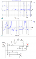
OTOH, the following is also esoteric ( but I've added some resistance in various places to increase the overall impedance level ).
- this was done using a pair of your older files ( 1.45" was used as the offset > so I don't know how accurate this will translate ultimately ).
It's presented more as an example on how to make some FR compromises ( while increasing overall impedance ).
I can't see beyond 20K and can only guess that the impedance at 50K ( or even 100K ) is still alright ( & stable ) for a typical PA amp.

- You might want to spend some time redesigning according to those safer principals ( as seen in the first handful of posts ).
OTOH, the following is also esoteric ( but I've added some resistance in various places to increase the overall impedance level ).
- this was done using a pair of your older files ( 1.45" was used as the offset > so I don't know how accurate this will translate ultimately ).
It's presented more as an example on how to make some FR compromises ( while increasing overall impedance ).
I can't see beyond 20K and can only guess that the impedance at 50K ( or even 100K ) is still alright ( & stable ) for a typical PA amp.
Attachments
Last edited:
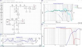
Another circuit to have look at. The circuit was designed based on the last measurements and delay findings (post#37). The biggest difference can be seen around 4kHz. The original circuit trace (green) shows a 5dB raise which likely comes from breakups of the Monacor driver. New midwofer filter has 10dB more attenuation @4kHz and this area is left to be served by the tweeter.
The circuit doesn't look simple but don't be cheated with the number of coils, wchih is 5, as 2 of them are microscopic and cost little more than resistors.
The circuit doesn't look simple but don't be cheated with the number of coils, wchih is 5, as 2 of them are microscopic and cost little more than resistors.
Attachments
- Status
- This old topic is closed. If you want to reopen this topic, contact a moderator using the "Report Post" button.