Hi everyone,
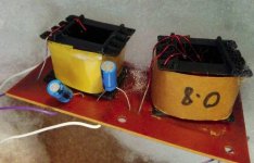
I was checking some old speakers I had in storage and noticed that one of the tweeters wasn't working. Opening both speakers, I saw that the crossover circuit has two caps, both 10uf. One speaker has caps rated 25V (one of them had exploded) and the other speaker has them rated 50V. Caps in both speakers are all electrolytic. This finding made me suspicious of the whole crossover circuit.
The speaker elements were made in Germany by Isophon in the early 80s, but were most likely assembled into a cabinet locally by the importer and may have been worked on at some point before I received them.
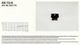
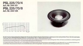
I couldn't find exact documentation for the woofer (p-225-35-8) and tweeter (kk7/8). This is the closest I got.
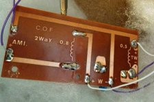
Judging by these photos, can you tell if this circuit makes sense for these speakers in this configuration? If the inductor values ( 0.8mH and 0.5mH) make sense, what values should be chosen for the capacitors? What crossover frequency is a safe bet? Is it normal to have two different inductor values in a crossover circuit?
I'm sorry if I offend you with my ignorance. I just want to try and revive these speakers. Any information or opinion will be greatly appreciated.
I was checking some old speakers I had in storage and noticed that one of the tweeters wasn't working. Opening both speakers, I saw that the crossover circuit has two caps, both 10uf. One speaker has caps rated 25V (one of them had exploded) and the other speaker has them rated 50V. Caps in both speakers are all electrolytic. This finding made me suspicious of the whole crossover circuit.
The speaker elements were made in Germany by Isophon in the early 80s, but were most likely assembled into a cabinet locally by the importer and may have been worked on at some point before I received them.
I couldn't find exact documentation for the woofer (p-225-35-8) and tweeter (kk7/8). This is the closest I got.
Judging by these photos, can you tell if this circuit makes sense for these speakers in this configuration? If the inductor values ( 0.8mH and 0.5mH) make sense, what values should be chosen for the capacitors? What crossover frequency is a safe bet? Is it normal to have two different inductor values in a crossover circuit?
I'm sorry if I offend you with my ignorance. I just want to try and revive these speakers. Any information or opinion will be greatly appreciated.
Last edited:
It's not unusual to use different values. The woofer and tweeter require different filtering.
If it uses one capacitor and one inductor per driver I would guess that it has been thought out, to some minimum level at least. Ie the crossover frequency is probably a reasonable choice.
The choice of Voltage ratings might be OK considering the two capacitors are doing different jobs,
If it uses one capacitor and one inductor per driver I would guess that it has been thought out, to some minimum level at least. Ie the crossover frequency is probably a reasonable choice.
The choice of Voltage ratings might be OK considering the two capacitors are doing different jobs,
Thanks for responding. I'm sorry for not being clear about the voltages - what I meant was that one speaker (let's call it the left one) has a different voltage rating on its caps than the right one. This raises the following possibilities:
1. The capacitors are original and 25V is sufficient, so it doesn't matter if the others are rated for 50V.
2. The 25V capacitors are not original, but their capacitance values are according to spec.
3. All the capacitors were used for their availability and price alone. 10uf was chosen as a general "safe" value and same goes for the type of capacitors (electrolytic shouldn't be used for this application, right?)
4. The entire crossover circuit was just dropped there, either by the importer or by a random customer, as a "one size fits all". It shouldn't be considered as reference for anything and needs to be replaced with different components altogether.
That's why I'd like to find out if this circuit makes sense for this speaker configuration. All the online calculators I saw only ask for speaker impedance and crossover frequency as variables, and they always give out identical values for a pair of capacitors or inductors. Is there a way to infer the crossover frequency according to inductance and capacitance?
Most likely one of the caps burst and was replaced with a different part (same uF, different voltage). Crossover capacitors are very unlikely to get damaged by voltage (it's of course possible, but you'd be surprised how low the voltage across the capacitor is likely to get in normal use). More likely, it's from I^2*R losses overheating the cap -- older electrolytic caps can get a lot of excess R in them, which can lead to heat and bursting.
bwaslo - the thing is, the second cap on the same board is also 25V and the board in the second speaker has both caps at 50V. I believe that all caps are the original ones because these speakers were hardly used and spent most of their lives in storage. Still, maybe the capacitance is fine and I'll just replace all of them with some metalized polypropylene ones of the same value.
AllenB - Thanks for the numbers. Does it seem generally acceptable for these drivers? I know there's no telling without the exact data sheets, but is it at least a sane approximation?
Thanks again for the help, everyone. I really appreciate it.
AllenB - Thanks for the numbers. Does it seem generally acceptable for these drivers? I know there's no telling without the exact data sheets, but is it at least a sane approximation?
Thanks again for the help, everyone. I really appreciate it.
It is not so unusual to find caps of different brands on the crossover boards of a pair of otherwise identical speakers. As for the Isophon drivers, I never tried them but they should be worth a go. Maybe a small resistor on the tweeter if you switch to poly caps, which I would do.
So 10uf it is, then.
phivates - What would be the purpose of this resistor? Is it necessary when switching to non-polarized caps? Where exactly should I place it in the circuit and what would be a "small" value? Sorry for all the basic questions. I know it's not fun and easy to deal with absolute laymen when giving advice.
phivates - What would be the purpose of this resistor? Is it necessary when switching to non-polarized caps? Where exactly should I place it in the circuit and what would be a "small" value? Sorry for all the basic questions. I know it's not fun and easy to deal with absolute laymen when giving advice.
AllenB would be the one to ask about this - electrolytic caps have an inherent characteristic called esr, which stands for equivalent series resistance. Film caps not so much - but they are reliable over the long term and are considered by some (not all) to be cleaner sounding. So to maintain the same tweeter output after swapping to poly capacitors, you might find the high frequencies a bit too bright. You could lose a year of your life reading everything that has been written on this topic. I like the long term reliability aspect.
Poly stands for polyester or polypropylene. They are non-polar, as are the electrolytics in your crossovers.
Poly stands for polyester or polypropylene. They are non-polar, as are the electrolytics in your crossovers.
Last edited:
A small value would be a fraction of an ohm if the capacitors change things, but I can't see any great deal of accuracy in the original design so I guess you could make a subjective call yourself. Maybe you'd be inclined to use up to a few ohms for whatever reason.
If you just put in resistors the response can be altered slightly other than just the level. Not necessarily enough to be a problem in this early stage but you might try a resistor in different positions. Maybe first you could try it before the capacitor. Later you could try it between the capacitor and the driver. The first option would create less unexpected change.
If you just put in resistors the response can be altered slightly other than just the level. Not necessarily enough to be a problem in this early stage but you might try a resistor in different positions. Maybe first you could try it before the capacitor. Later you could try it between the capacitor and the driver. The first option would create less unexpected change.
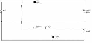
It's actually a fairly standard sort of configuration.
What we have here is a 0.8mH coil on the metal dustcap (!) 8" bass to roll it off a bit and subjectively boost the bass.
Then a second order tweeter filter on a 1" soft dome. Usually around 3kHz. Coil is possibly around 0.5mH. Everybody has got it wrong on the 75mm chassis 1" dome tweeter capacitor. It's actually two 10uf electrolytic polars connected back to back to make a 5uF NP type.
So, me, I'd just replace the twinned tweeter capacitors with a 5uF non polar electrolytic at 5uF/50V or so. 4.7uF/50V will do.
AFAIK, this is a positive polarity filter, which will sound less echoey or phasey than negative polarity.
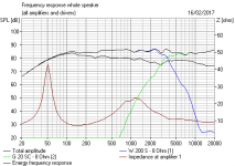
Last is a sim of how this sort of speaker works. If all goes well.
What we have here is a 0.8mH coil on the metal dustcap (!) 8" bass to roll it off a bit and subjectively boost the bass.
Then a second order tweeter filter on a 1" soft dome. Usually around 3kHz. Coil is possibly around 0.5mH. Everybody has got it wrong on the 75mm chassis 1" dome tweeter capacitor. It's actually two 10uf electrolytic polars connected back to back to make a 5uF NP type.
So, me, I'd just replace the twinned tweeter capacitors with a 5uF non polar electrolytic at 5uF/50V or so. 4.7uF/50V will do.
AFAIK, this is a positive polarity filter, which will sound less echoey or phasey than negative polarity.
Last is a sim of how this sort of speaker works. If all goes well.
Attachments
Last edited:
Good call, Steve! I was going mad trying to compare the PCB to other second order crossover schematics. Thank you and everyone involved for taking the time to help out. You're making the internet and the world a better place by sharing your knowledge so generously.
By the way, the actual drivers in my speakers are not identical to the ones I found the datasheets for. I don't think my woofers have a metal dust cap. Well, it isn't shiny, at least.
I'll try to update after sourcing and installing the capacitors, for posterity's sake.
By the way, the actual drivers in my speakers are not identical to the ones I found the datasheets for. I don't think my woofers have a metal dust cap. Well, it isn't shiny, at least.
I'll try to update after sourcing and installing the capacitors, for posterity's sake.
- Status
- This old topic is closed. If you want to reopen this topic, contact a moderator using the "Report Post" button.
- Home
- Loudspeakers
- Multi-Way
- Is this crossover right for these two-way speakers?