EDIT: I've added some data and screen shots to post #6 along with questions about how I'm trying to model this in Hornresp...any help would be appreciated.
I am trying to work toward a solution for bass reinforcement of a speaker project I've cobbled together from different items I picked up in the swap meet, Craigslist etc.
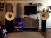
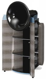
The core of the project is some Oris 200 horn lenses. They appear to have been parts let go when the US distributor shut down.
Currently I have some Tang Band W8 1808 drivers mounted in them. I made some rear chambers but left them open as I had read of people having success with the TBs in an open baffle application. I figured since I wasn't sure about back chamber design I'd avoid the issue. So I guess they are sort of set up open baffle or more likely H frame? They actually sound very good even though they are in what I am sure is a sub-optimal room and location.
At this point I'd like to try and figure out if it is worth while trying to modify and finish a dipole bass project I started a while back to integrate with the Tang Band/Oris horn combination.
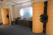
My project was based on Nelson Pass's Slot Loaded open baffle article. Before I even got the OB bass chambers cut out I was wondering about the idea of using a waveguide connected to them instead of a flat baffle.
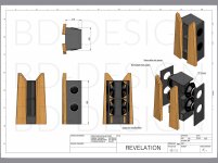
Sure enough, I came across several designs after that where BD was integrating waveguides with OB and slot loaded designs. The latest I came across, the "Revelation", gave up on the waveguide and seems to be a complicated slot loading arrangement. I have no interest in buying the expensive BMS drivers it is based on.
Instead, I'd like to try and model the chambers I've built with the drivers I got for the SLOB project with different baffles/waveguides to see if they will actually provide any benefit.
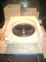
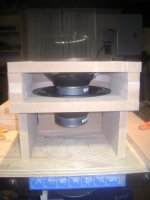
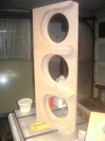
The chambers were built individually for driver pairs to have an outlet that is equal to 1/3 of the speakers Sd they are loaded with in a push/pull offset arrangement. This translates to a chamber opening of 2.25" X 8". They have a depth of 9" and the back of the chamber matches the circumference of the speaker frame.
I have no idea if it is possible to even model this push/pull dipole arrangement in Hornresp. I haven't used Hornresp in a while and forgot most of what I learned from the Kickstart article. I still have the article and am planning to reread and familiarize myself, but this is probably beyond it's scope.
Here is the data that was published by Parts Express where I purchased these drivers on buyout.
Product Specifications
Nominal Diameter8"
Power Handling (RMS)40 Watts
Impedance12 ohms
Frequency Response40 - 3,500 Hz
Sensitivity91.5 dB 2.83V/1m
Voice Coil Diameter1"
Thiele-Small Parameters
Resonant Frequency (Fs)43 Hz
DC Resistance (Re)10.9 ohms
Voice Coil Inductance (Le)1.93 mH
Mechanical Q (Qms)2.57
Electromagnetic Q (Qes)0.72
Total Q (Qts)0.56
Compliance Equivalent Volume (Vas)2.7 ft.³
Maximum Linear Excursion (Xmax)2 mm
I've attached some pictures of my horns, the chambers and drivers and also some of the BD products as a reference to what I've been discussing. Any help or guidance that can be offered is greatly appreciated.
Kevin
I am trying to work toward a solution for bass reinforcement of a speaker project I've cobbled together from different items I picked up in the swap meet, Craigslist etc.
The core of the project is some Oris 200 horn lenses. They appear to have been parts let go when the US distributor shut down.
Currently I have some Tang Band W8 1808 drivers mounted in them. I made some rear chambers but left them open as I had read of people having success with the TBs in an open baffle application. I figured since I wasn't sure about back chamber design I'd avoid the issue. So I guess they are sort of set up open baffle or more likely H frame? They actually sound very good even though they are in what I am sure is a sub-optimal room and location.
At this point I'd like to try and figure out if it is worth while trying to modify and finish a dipole bass project I started a while back to integrate with the Tang Band/Oris horn combination.
My project was based on Nelson Pass's Slot Loaded open baffle article. Before I even got the OB bass chambers cut out I was wondering about the idea of using a waveguide connected to them instead of a flat baffle.
Sure enough, I came across several designs after that where BD was integrating waveguides with OB and slot loaded designs. The latest I came across, the "Revelation", gave up on the waveguide and seems to be a complicated slot loading arrangement. I have no interest in buying the expensive BMS drivers it is based on.
Instead, I'd like to try and model the chambers I've built with the drivers I got for the SLOB project with different baffles/waveguides to see if they will actually provide any benefit.
The chambers were built individually for driver pairs to have an outlet that is equal to 1/3 of the speakers Sd they are loaded with in a push/pull offset arrangement. This translates to a chamber opening of 2.25" X 8". They have a depth of 9" and the back of the chamber matches the circumference of the speaker frame.
I have no idea if it is possible to even model this push/pull dipole arrangement in Hornresp. I haven't used Hornresp in a while and forgot most of what I learned from the Kickstart article. I still have the article and am planning to reread and familiarize myself, but this is probably beyond it's scope.
Here is the data that was published by Parts Express where I purchased these drivers on buyout.
Product Specifications
Nominal Diameter8"
Power Handling (RMS)40 Watts
Impedance12 ohms
Frequency Response40 - 3,500 Hz
Sensitivity91.5 dB 2.83V/1m
Voice Coil Diameter1"
Thiele-Small Parameters
Resonant Frequency (Fs)43 Hz
DC Resistance (Re)10.9 ohms
Voice Coil Inductance (Le)1.93 mH
Mechanical Q (Qms)2.57
Electromagnetic Q (Qes)0.72
Total Q (Qts)0.56
Compliance Equivalent Volume (Vas)2.7 ft.³
Maximum Linear Excursion (Xmax)2 mm
I've attached some pictures of my horns, the chambers and drivers and also some of the BD products as a reference to what I've been discussing. Any help or guidance that can be offered is greatly appreciated.
Kevin
Attachments
Last edited:
I am trying to work toward a solution for bass reinforcement of a speaker project I've cobbled together from different items I picked up in the swap meet, Craigslist etc.
Mods, can this post be split off as a separate thread?
Chromenuts, this thread is for discussing the Hornresp application and suggestions for upgrades or bug-fixes.
Given the proximity to the floor, its clearly in 2pi space.
A more detailed model would consider the horn in 4pi space and then analyze the contributions from the room boundaries.
Consider the floor: The reflection from the floor is the same as would be produced by a horn built into the floor - a mirror image horn. That reflection doubles the level but its the same 6 db gain you get from modelling it in 2pi space.
I apologize if I've posted in the wrong place. I thought the thread was for asking questions about using Hornresp. If it would be more appropriate for it to be split off as a separate thread, please proceed and let me know where to look for it.
I think the biggest issue for me is not knowing how to model the push/pull speaker arrangement at the beginning of the horn/waveguide.
I think the biggest issue for me is not knowing how to model the push/pull speaker arrangement at the beginning of the horn/waveguide.
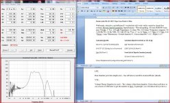
I've spent several afternoons trying to figure out how to model these waveguides that are being mounted to the front of dipole speaker arrangements (see pics in first post). I've attached a screenshot of my blundering.
I tried to make the model based on a single chamber loaded with 2 offest drivers wired in series. It is modeled in 2Pi space. There would be three of these chambers ultimately stacked and wired series/parallel to produce an 8 Ohm load. So the response for the top and middle stack would obviously be different. I wanted to start with a simpler model of what just one chamber with a waveguide would do.
In my scenario, as I mentioned, I want to use the chamber I created originally for a SLOB project. There is a front exit to the chamber that is approximately 1/3 of the Sd of the 2 drivers that the chamber is loaded with (a basic guideline that was given in the original write up of the SLOB project). Mine may be a little smaller than that based on the estimated calculations.
I had no manufacturer's spec for Sd of these drivers, so I calculated a number based on a formula I found in another thread on here devoted to the topic of calculating Sd. It fell within "average" Sd numbers I found for 8 inch drivers on various lists.
I found an online calculator that estimated driver displacement in order to have some kind of number to enter in the Vtc field. To be honest, I have no idea how accurate the number is or whether I was supposed to double it because the chamber is loaded with two drivers in a push/pull arrangement. I was using this based on my vague understanding of the description in the Kickstart article of what Vtc was.
I have no idea what to do about rear chamber specifications. In actuality there is NO rear chamber. I tried to imagine what to enter given the requested parameters for either a sealed or vented rear chamber.
The only idea I could come up with was to make all the chamber parameters as close to infinite as possible? So I entered 99999.99 in all those fields. Something tells me this is NOT the correct way to do this.
After screwing around for quite some time the only decent looking output I could get based on the inputs I had and Hornresp calculating some of what I didn't have was with a combination Conical/Exponential horn that seemed much longer than I would want or what I've been looking at when I see this arrangement of dipole/waveguide.
The profiles used in what I'm seeing (BD Design) most definitely do NOT look conical in my opinion. Their flare rates look to be higher than my exponential attempt and more like a LeCleach or Tractix.
I wasn't able to model a multi segment offset driver arrangement that represented the actual chamber I have with either of those flares.
The first segment with offset drivers only extends to the center of the driver. The only way I could find to extend the chamber with a 0 degree flare to the point that it actually reaches at the other edge of the driver was with a conical flare.
I couldn't figure out how to add anything but a conical/exponential/parabolic flare at that point.
When I tried to just plop a LeCleach or Tractrix on without properly trying to model the chamber as it is, the frequency response output was pretty much garbage. Granted, I have no idea if any of the parameters are set properly relating to the chamber or throat either.
Any help here would be greatly appreciated...I'm trying.
Attachments
I was hoping someone could give me a tip here on how the rear chamber should be handled in Hornresp with this dipole arrangement?
I tried the Hornresp thread already, but they told me that thread was devoted to sorting technical issues with the program. They split my question off to this thread.
Does anyone know of a thread that helps with learning how to use Hornresp and dealing with issues like this?
The closest thread my search found was something devoted to ripple/dipole exploration that went completely off on a tangent and ended up being a thread about building a huge tapped horn with a waveguide.
If you have OB slot loaded woofers then they have no rear chambers. Per horn resp help file, the way to model this is not to specify a rear chamber (set Vrc to 0). (search help for "front-loaded horn" Then HR will calculate the combined output by default but allow you to select the direct radiator or horn output using the output tool which is available in the tools menu when looking at the acoustical power screen. When you first select combined, a popup will ask you to set the acoustic path length between the direct and horn outputs. After that, things might start to make sense.
Do you have the waveguides for the mids?
Not sure what you mean by "waveguides for the mids"...unless your talking about the Peerless W8-12t 12p drivers that I want to use in the dipole chambers I already built and add a waveguide to for bass under the Oris horns which are loaded with the Tang Band W8 1808?
If so, no waveguides exist yet...that is what I am trying to model in Hornresp to see if it is worth making and adding a waveguide to the front of the dipole bass chambers in place of a flat baffle which would otherwise simply make it the SLOB project it started out as.
Thank you for the tip nc535.
I had tried specifying Vrc as 0, but wasn't sure if that was correct. I assume I would also specify Lrc as 0 as well?...and I suppose it doesn't matter if the chamber is specified as sealed or vented if all parameters associated with the chamber are set to 0?
I will try to drill down into help and as you mentioned.
Hi chromenuts,
It's actually not necessary, but it does make the chamber inputs look a bit neater") . If either Vrc or Lrc is set to zero, Hornresp assumes that there is no rear chamber.
. If either Vrc or Lrc is set to zero, Hornresp assumes that there is no rear chamber.
Correct. If in doubt at any time as to what design you have specified, simply check the schematic diagram to see what has been included.
Kind regards,
David
I assume I would also specify Lrc as 0 as well?
It's actually not necessary, but it does make the chamber inputs look a bit neater
. If either Vrc or Lrc is set to zero, Hornresp assumes that there is no rear chamber.I suppose it doesn't matter if the chamber is specified as sealed or vented if all parameters associated with the chamber are set to 0?
Correct. If in doubt at any time as to what design you have specified, simply check the schematic diagram to see what has been included.
Kind regards,
David
- Status
- This old topic is closed. If you want to reopen this topic, contact a moderator using the "Report Post" button.
- Home
- Loudspeakers
- Multi-Way
- Modeling dipole bass with waveguide?