If you made for example, C2 smaller and/or L5 larger you'd see the mid driver peak near 400Hz reduced. Maybe try making L2 smaller for the mid driver top end. See if you can give them a little more symmetry as this makes it easier. Have a play with it.
Attachments
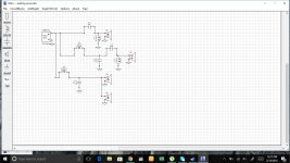
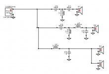
Crossover Design
Would this be considered an ideal response, i have gone with a 3 way 2nd order crossover. As you can see i have modeled the bandpass with out inverting polarity. I saw a slight peak in impedance at 250hz, can somebody help me remedy this.I am new to this, can you please check the frequency and impedance response and tell me if its proper so i can go ahead with fabrication
The drivers used are as follows,
Tweeter-Dayton Audio PT2C-8 Planar Tweeter
Midrange - Dayton Audio DC50FA-8 Classic Series 2" Dome Midrange
Woofer- Dayton Audio DC300-8 12" Classic Woofer (using 2 woofers in paralle)
Going for a TMWW configuration
Attachments

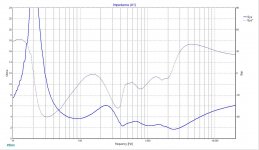
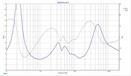
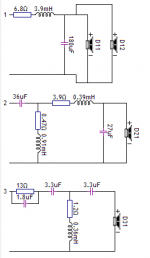
i have arrived at this design. but why does the impedance drop to 2 ohms? the woofers which are individual 8 ohms, will be wired in parallel, have i incorporated that into the design?
Attachments


 Please do not start multiple threads on the same topic, threads merged.
Hi,
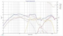
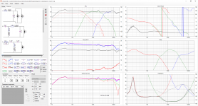
I had a go but will be interested to see what others come up with. The mid range has a very low impedance especially for something that claims to be 8 ohms.
I have attenuated the bass significantly to match the mid range, however once you have baffle loss it probably won't be required.
If you can give an estimate of the box volume. The dimensions of the baffle and the approximate locations of the drivers I can create a much more accurate simulation.
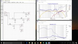
I would not try to build the simulation below it is just a first draft as it does not include baffle loss or bass alignment. To create a simulation that is close to actual you either need to simulate the baffle or even better have actual measurements of the drivers in the box.
Regards,
Andy
I had a go but will be interested to see what others come up with. The mid range has a very low impedance especially for something that claims to be 8 ohms.
I have attenuated the bass significantly to match the mid range, however once you have baffle loss it probably won't be required.
If you can give an estimate of the box volume. The dimensions of the baffle and the approximate locations of the drivers I can create a much more accurate simulation.
I would not try to build the simulation below it is just a first draft as it does not include baffle loss or bass alignment. To create a simulation that is close to actual you either need to simulate the baffle or even better have actual measurements of the drivers in the box.
Regards,
Andy
Attachments
@Gfiandy here are the following
1. Box will be a sealed box with internal dimension of 13×12×54
2. Baffle will also carry dimensions of 14.5×13.5×55.5(external)
3.will be using 1" inch ply for baffle rest will be 3/4" inch for the rest.
4. I plan to go with a TMWW configuration, alignment will start 3 inches from too edge and every driver will be spaced 1.5 inch away from then onwards
Ok, I have done some baffle simulations.
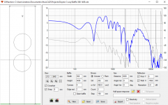
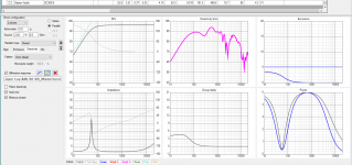
The normal approach when designing speakers is to use anechoic measurements and correct for that. The first graph shows an anechoic measurement of the baffle diffraction and loss assuming a listening distance of 3m.
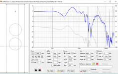
As these look like they will be floor standers the second simulation includes the floor gain.
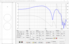
The third option (Which would be very difficult to correct) is for the floor and assuming you have a wall 1.5m away.
None of them include room pressure gain which increases bass at quite low frequencies if the room is relatively small and has stiff walls, this usually isn't much of a problem as it tends to correct for the bottom end roll off of the speaker.
Which one would you prefer me to use for the simulation? My preference would be anechoic as its much easier to cope with. With the others the best I can really do is assume an average line through the response as you cannot really correct out the dips anyway. However as you can see if might be worth allowing some low frequency dip to allow for the floor gain.
Do not worry about the high frequency part of the repose this is just for the bass drivers the midrange and tweeter will need separate simulations.
Regards,
Andy
The normal approach when designing speakers is to use anechoic measurements and correct for that. The first graph shows an anechoic measurement of the baffle diffraction and loss assuming a listening distance of 3m.
As these look like they will be floor standers the second simulation includes the floor gain.
The third option (Which would be very difficult to correct) is for the floor and assuming you have a wall 1.5m away.
None of them include room pressure gain which increases bass at quite low frequencies if the room is relatively small and has stiff walls, this usually isn't much of a problem as it tends to correct for the bottom end roll off of the speaker.
Which one would you prefer me to use for the simulation? My preference would be anechoic as its much easier to cope with. With the others the best I can really do is assume an average line through the response as you cannot really correct out the dips anyway. However as you can see if might be worth allowing some low frequency dip to allow for the floor gain.
Do not worry about the high frequency part of the repose this is just for the bass drivers the midrange and tweeter will need separate simulations.
Regards,
Andy
Attachments
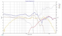
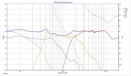
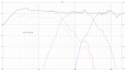
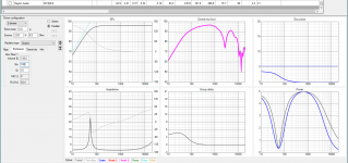
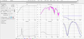
Another view of the responses the different diffraction responses combined with the two bass drivers in a 138L box (which is what I make for enclosure).
The purple line is the combined response again don't worry to much about the high frequency response the bass driver will be filtered at around 500 - 600 Hz.
Update.
Just saw your message what I will do in that case is go with the anechoic but not try to get the response flat down to Fs and allow some roll off to account for floor and wall + room gain.
Attachments
- Status
- This old topic is closed. If you want to reopen this topic, contact a moderator using the "Report Post" button.
- Home
- Loudspeakers
- Multi-Way
- need help designing a 3-way crossover